
Variable power supply from 2v to 15v 1A
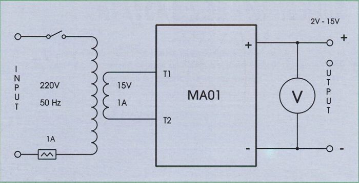
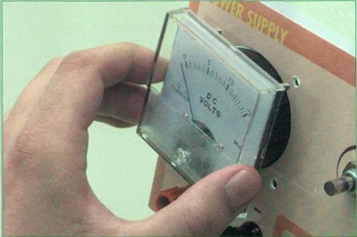
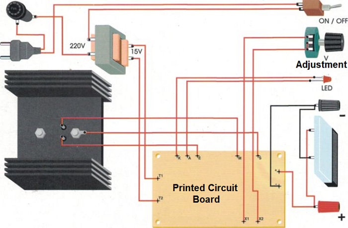
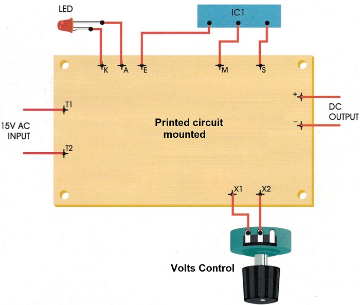
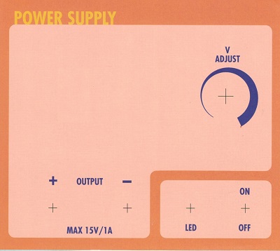
The power source is one of the most useful elements in the laboratory. This particular model allows you to have any stabilized and adjustable DC voltage between 2 and 15 Volts, with a maximum output current of 1A. This source uses the MA-01 power module. With this are added the power transformer, a switch for switching on/off and a protection fuse. In addition, there is the potentiometer which adjusts the voltage requirements and a voltmeter connect in order to check the output voltage at any time. Everything must be placed in a box. To improve the aesthetics and to indicate the function of each element of the front panel a label is provided to be glued to the panel as per the figure above. For this operation, we recommend using double-sided tape. This small device is very useful because it fulfils almost all the power supply needs of small devices or battery-powered circuits. Furthermore, using an integrated circuit, it is not necessary to insert adjustment elements (thanks to this), the start-up is immediate. However, before connecting the appliance to the mains, it is advisable to carry out a conscientious review of all internal connections. Figure 1 below shows in general all the connections
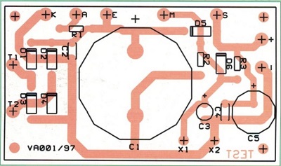
Figure 1
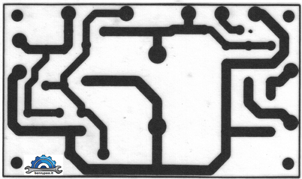
The components
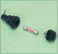
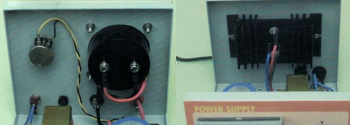
Two perforations will be made in the rear panel of the instrument; one will be used to allocate the fuse and the output of the network cable. The cable must be protected from any rubbing against by inserting a rubber grommet. The DC voltage output terminals, positive and negative, must be isolated from the front panel.
The internal of front panel; the connections between the output terminals and the printed circuit board must be made with cables of at least 1 mm of section. The '+' and '-' symbols placed near all the connection terminals indicate the polarity.
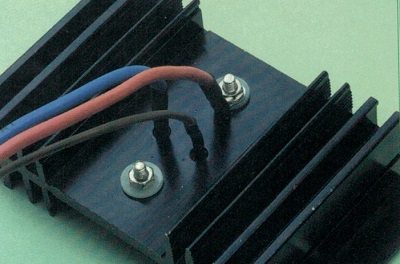
The heatsink can be installed inside the box, but holes must be made on both sides upper and lower of the box, to allow the passage of air. See figures below
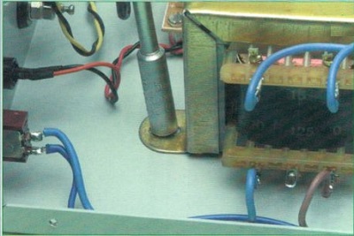
Some advice The connections of the network cables must be made as follows: one of the conductors is connected to a terminal of the fuse holder, while the other terminal of the fuse should be connected to terminals of the transformer (the one identified as 220V). The other input conductor is brought to the switch, then the output of the switch should be connected to the terminal of the transformer. These connections must be perfectly insulated from the box. The yellow/green safety ground wire will be connected to the metal part of the case with a screw. We recommend carrying out these operations at the end, with the cable very folded and close to the appliance, because if we leave the plug far from the appliance and free, someone could accidentally insert it into a mains socket and cause you to suffer a dangerous current.
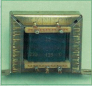
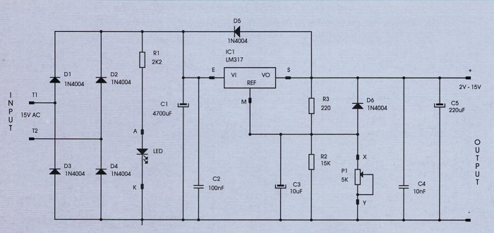
The circuit This module allows starting from an alternating voltage which is 15 Volts, and obtain a continuous and adjustable output voltage from 2 to 15 Volts, with a maximum current of 1A. By adding a transformer, a container and some accessories, we can build different power sources. The integrated circuit used in the design of this module can be used to build fixed or adjustable power supplies with an output voltage between 1.2 and 35 Volts, with a maximum output current of 1.5 Amps. With the values we have chosen for the components, however, we limit the adjustment of the output voltage between 2 and 15 Volts and the output current of 1 Amp maximum; it is also assumed to use a power transformer with a secondary of 15 Volt and 1 Ampère. The input voltage of a transformer must be chosen according to the voltage of the network; in Europe, the voltage is usually 220V / 50Hz. If we choose a fixed output voltage, the power transformer must deliver an output voltage three times higher than the one you want to achieve.
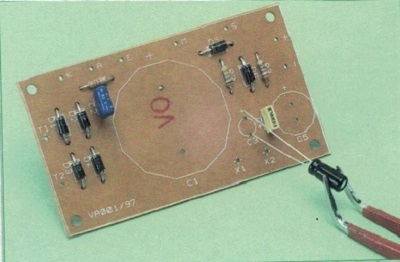
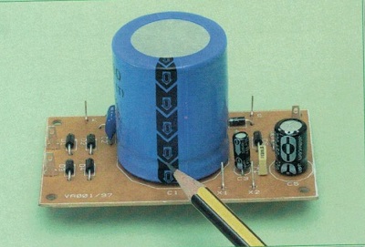
The first components to be installed on the plate are the smallest ones. The black diodes have a band that indicates the terminal corresponding to the cathode and must be made to coincide with the one printed on the plate. The capacitor C3 is electrolytic; the longer terminal must be inserted in the hole indicated on the serigraphy with the V sign.
Some advice The connections must be made with great care and make sure that you have properly connected the terminal of each component to the corresponding terminal. The secondary of the transformer must be connected to terminals T1 and T2; in this case, the two terminals are interchangeable.
Recommendations Do not try to change the fuse capacity. The power has already been tested and is 1 ampere if you need the board is available on this website This power supply can be controlled also via a microcontroller (PIC) and digital display. For more details contact via email
www.bennypass.it |
||||||||||||||||||


+(39) 347 051 5328
Italy - Kazakhstan


09.00am to 18.00pm
About
We offer the best and economical solutions, backed by 27+ years of experience and international standards knowledge, echnological changes, and industrial systems.
Our Services
Marketing Materials


Marketing Materials1


