
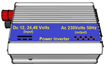
Inverter working principle (Solar Panel) The inverter is an electronic device that transforms a direct current into an alternating current, see Figure 1 below
Figure 1 In general, the inverters used in photovoltaics can be divided into two large families:
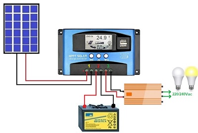
Figure 2
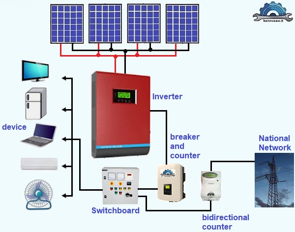
Figure 3 The differences between these two categories of equipment are technical and applicative, for this reason, the manufacturers have two separate product lines. Using the inverter in photovoltaic systems is clear: photovoltaic modules produce energy in the form of direct current, while the devices and user systems (TV, washing machines, refrigerators, routers, etc.) operate in alternating current. The electricity distribution network is also in alternating current (AC), and therefore it is necessary to make the energy produced compatible with that consumed. Basically, inverters for isolated services have the following characteristics:
Conversely, inverters for grid service must have other characteristics that can be summarized as:
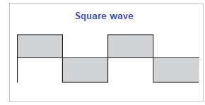
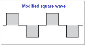
MPPT (Maximum Power Point Tracker) The search function of the maximum power point, is made through the MPPT (Maximum Power Point Tracker) function, can only be found in the inverters for the national network, as the inverters for isolated applications typically draw energy from the storage battery and therefore do not they interface directly with the photovoltaic generator. The MPPT device has the purpose of identifying moment by moment that particular point on the characteristic of the photovoltaic generator for which the power transfer to the load located downstream is maximum, i.e. towards the inverter. As the power of the photovoltaic varies instantaneously with the variation of irradiation and, more slowly, with the variation of the temperature. These variations cause the displacement of the maximum power point, which results in the practical impossibility of predicting its location by controlling the inverter with traditional calculation tools. Operation The low-cost ones "transform" the 12/24 Volts voltage into 220 Volts alternating voltage in order to power low-power electronic devices, and is conceptually composed of two stages; the first raise the voltage from 12/24 Volt to a voltage of about 300 Volts. This voltage, in the simplest and usually cheaper inverters, also called "modified sine wave", is simply modulated by two digital signals, one controls the polarity and one the presence or absence of the output voltage, with the result that the output there is something similar to a square wave rather than a sine wave (see Figure 4 below).
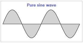
In pure sine wave inverters, which is what I recommend, the second stage is more complex, the 300-volt voltage of the first stage is pulse-modulated (PWM) at a very high frequency and then filtered, the result is that in output, there is a sinusoidal voltage whose quality is often higher than that of the mains. For more details click here to see my project of a pure sine wave inverter (see Figure 6 below)
Figure 6 The Stand-by of the inverter is used to disconnect the electrical system when there is no absorption for a certain number of minutes and reactivate it when the system requires energy.
Choice of the inverter
www.bennypass.it |

+(39) 347 051 5328
Italy - Kazakhstan


09.00am to 18.00pm
About
We offer the best and economical solutions, backed by 27+ years of experience and international standards knowledge, echnological changes, and industrial systems.
Our Services
Marketing Materials


Marketing Materials1


