
Photovoltaic system architecture Without batteries The architecture of a photovoltaic system connected to the grid can be of two types: without storage or with storage (batteries). Without batteries The photovoltaic system connected to the electricity grid without batteries is made up of all the modules and the inverter.
Figure 1 The inverter, whose characteristics are different from those used for isolated photovoltaic systems, must convert the direct current from the solar panels into alternating current with the same voltage and frequency as the electricity network grid which is connected to it. In other words, the photovoltaic system works in parallel with the national grid, becoming a small generator. itself. So photovoltaics produce the energy which can be used directly to the equipment connected (television, washing machine, light bulbs, etc.) or is fed into the network. The electric current generated by the panels is read by the meter located downstream of the generator (PV). The current connected to the network or taken is read by a bidirectional meter installed near the withdrawal point. For more details see the figure below
Theoretical operation of the photovoltaic system in an exchange function During daylight hours, users consume the energy produced by the photovoltaic system (see Figure 3 below)
At night or in low light conditions, the user draws energy from the electricity grid (see figure 4 below)
If the system produces more than what is required by the user, the excess energy will be fed into the network grid and read from the bidirectional meter (See Figure 5 below).
The components for a basic system are:
Sizing, configuration, and calculation This example assumes a small-sized system typical of a single-family house with two people. The systems are connected to the public low-voltage network with TT-type grounding systems, where the masses of the 'photovoltaic system, which instead remains isolated in its active parts. It is also assumed that the prospective short-circuit current supplied by the public network is about six kA between phase / neutral (single-phase) In our case, the contract with the electricity company is 3 kW, and the annual consumption is 2500 kWh. Sizing There are two criteria for sizing a system connected to the electricity grid:
In general, the amount of energy produced by solar panels must be equal to or less than that supplied by the distributor to the customer. Example of calculation of the power in KWp The power of the photovoltaic system is the ratio between the customer's consumption and an estimate of the local photovoltaic production, taking into account the equivalent hours of sunshine. Sizing also must be considered. The system's efficiency will be 80%, in consideration of the various losses. The formula for calculating the maximum power of the photovoltaic is this:
Example of power sizing with self-consumption prevalence First, we calculate the equivalent hours of sunshine, which will be different depending on where the plant is located: let's suppose Milan (Italy) click on PVGIS you can see direct your country how many hours of sunshine. In our case, the annual daily average of solar radiation on a 30 ° inclined surface is 3.95 kWh. For example, if the annual consumption were 2,500 kWh using the formula:
The preliminary sizing example refers to the best conditions of orientation and exposure, that is to say: the inclination of 30 ° and orientation to SOUTH. If the user were in another region, the power would change. The annual national average in the SOUTH reports a value close to 1,280 kWh produced on average in a year for each kW of photovoltaic system power. In the North of Italy, the average is 1,100 kWh per peak kW. From the calculation previously seen in the North, it would be 1110 x 2.17 = 2,408 kWh per year. In line with our calculations, in the South with similar power, we will have 1280 x 2. 17 = 2777.6 kWh per year. Sizing by available area The sizing of the area available to install the photovoltaic panels according to the maximum power you need can be the true discrimination. Let's see how many square meters it would take to have a power of 2.5 kWp, using the formula. Assuming to use 280 Watt Polycrystalline modules in series, nine would be needed (280 x 9 = 2500 Watt) and, using the formula. It would take about 18.15m2, in Monocrystalline approximately 14.12 m², and 29.2 m² with amorphous silicon panels. Note if you put the panels in series or in parallel the Power is always the same (Power: P = V * I if the voltage increases, the current will decrease and vice versa). Technical characteristics of the 280 Wp 24 Volt photovoltaic panel (STC*) STC: (Standard Test Condition) Irradiation 1000W / m², Module temperature 25 ° C, Air mass 1.5.
Characteristics related to temperature NOCT: (Nominal Operation Cell Temperature) Sole 800W/m²; Temperatura ambiente 20°C; Velocità vento 1m/s
Let's assume that the minimum and maximum temperatures are -10 and +70. The standard reference temperature is 25 ° C; we calculate the voltage variation (at low temperatures, the photovoltaic voltage increases and decreases at high temperatures). To do this, I will use the following formula:
where: Vmp is the voltage at maximum power as per the manufacturer's technical specifications Kvoc is the Voc temperature coefficient, expressed in V / ° C, as per the manufacturer's specifications; to convert from (% / ° C) to (V ° / C) use the formula: Voc (V / ° C) = (% / ° C) * Voc / 100 = V / ° C 25 ° C is the manufacturer's standard test temperature; T.min and T.max are the minimum and maximum ambient temperatures of the installation site of the system. Voc is the Open Circuit Voltage (maximum voltage of a device). In our case the Vmp = 31.32 Volt, the Voc = 37.7 Volt, and the temperature coefficient of the Voc = -0.43% / ° C, which I transform into V / ° C using the formula: Voc (V / ° C) = (% / ° C) * Voc / 100 = -0.43 * 37.7 / 100 = - 0.162 V / ° C Voltage at maximum minimum power = Vmp (Maximum Temperature) = Vmp + [KVoc * (T.max. - 25 ° C)] = 31.32+ [-0.162 * (70-25)] = 24.03 Volt Voltage at maximum maximum power = Vmp (Minimum temperature) = Vmp + [KVoc * (T.min. - 25 ° C)] = 31.32 + [- 0.162 * (- 10-25)] = 37 Volt Maximum no-load voltage = Voc (Minimum temperature) = Voc + [KVoc * (T.min. - 25 ° C)] = 37.7+ [-0.162 * (-10-25)] = 43.3 Volt For safety, I will choose from the components of the photovoltaic system the greater value between the maximum no-load voltage (43.3 V) and 120% of the no-load voltage of the modules = 43.3 x 120% = 52 Volts; which will be the reference voltage. Electrical characteristics of the photovoltaic panels string
Coeff. temp. of the short-circuit current (KIsc) = - 0.32% / ° C = Isc (I / ° C) = (% / ° C) * Isc / 100 = -0.32 * 9.7 / 100 = -0.03 I / ° C
Recommendations Before buying or installing any solar panel it is important to read the datasheet to understand all the parameters as shown in our example. Ask questions to experts people and not the ones to do everything. for any doubt contact us here on the website.
www.bennypass.it
|
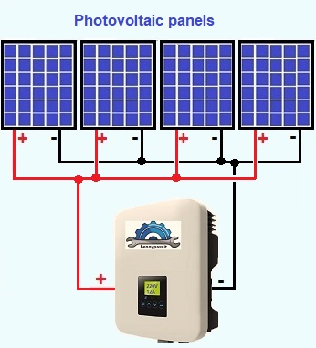
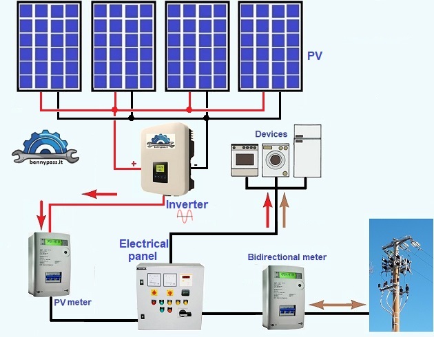
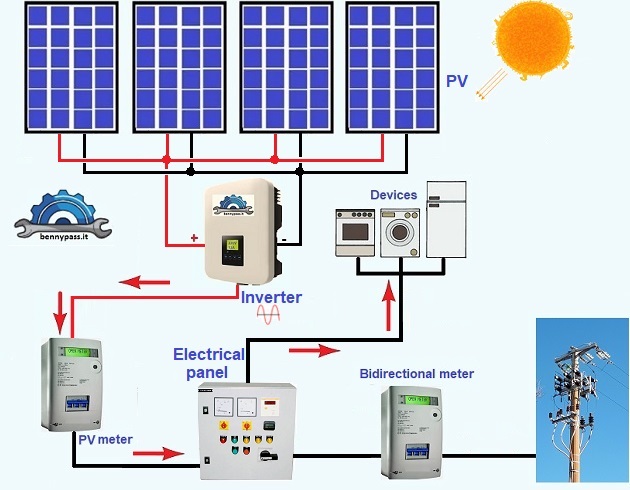
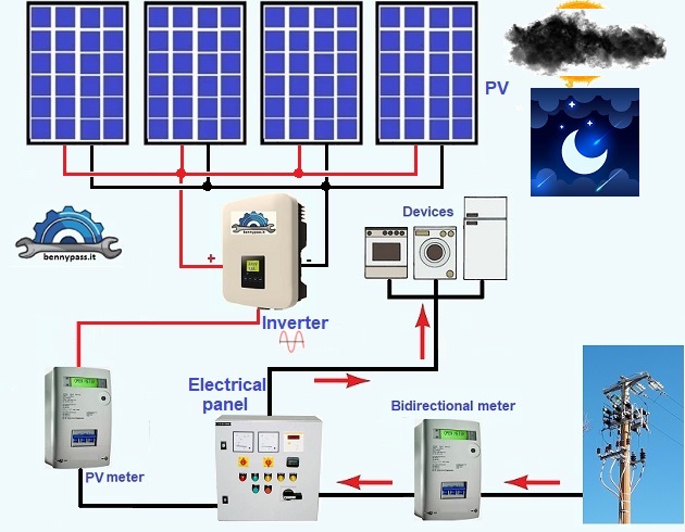
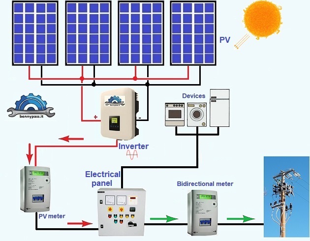
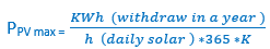
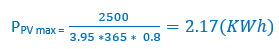
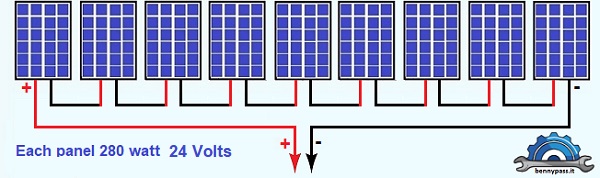 Figure 6
+(39) 347 051 5328
Italy - Kazakhstan


09.00am to 18.00pm
About
We offer the best and economical solutions, backed by 27+ years of experience and international standards knowledge, echnological changes, and industrial systems.
Our Services
Marketing Materials


Marketing Materials1


