
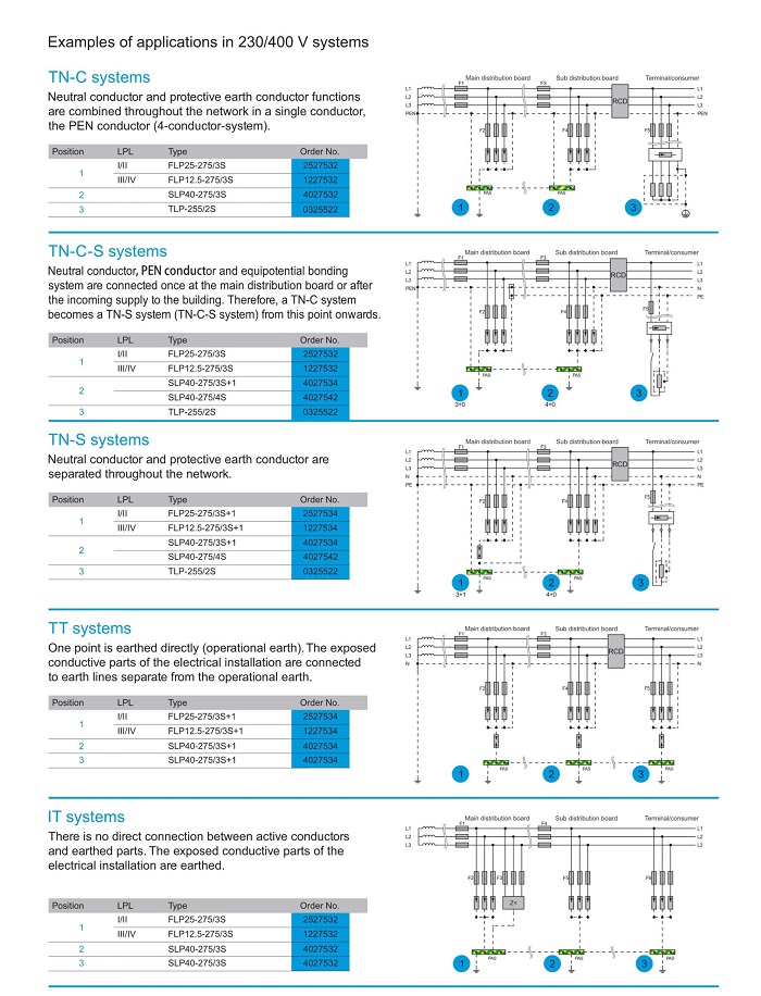
Power Supply System (TN-C, TN-S, TN-C-S, TT, IT) The basic power supply system used in the power supply for construction projects is a three-phase three-wire and three-phase four-wire system etc, but the connotation of these terms is not very strict. The International Electrotechnical Commission (IEC) has made uniform provisions for this, and it is called TT system, TN system, and IT system. Which TN system is divided into TN-C, TN-S, TN-C-S systems. The following is a brief introduction to various power supply systems. power supply system According to the various protection methods and terminologies defined by IEC, low-voltage power distribution systems are divided into three types according to the different grounding methods, namely TT, TN, and IT systems, and are described as follows in Figure 1.
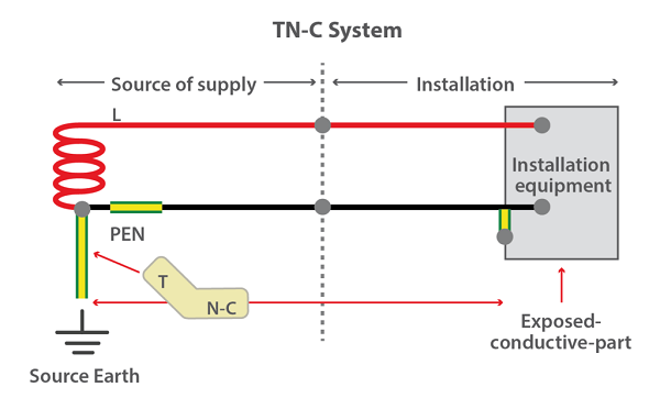
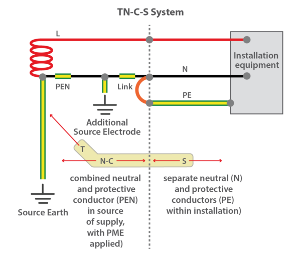
TN-C power supply system The TN-C mode power supply system uses the working neutral line as the zero-crossing protection line, which can be called the protection neutral line and can be represented by PEN. TN-C-S power supply system For the temporary power supply of the TN-CS system, if the front part is powered by the TN-C method, and the construction code specifies that the construction site must use the TN-S power supply system, the total distribution box can be divided at the rear part of the system. Out of the PE line, the features of the TN-CS system are as follows.
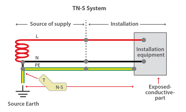
Through the above analysis, the TN-C-S power supply system is temporarily modified on the TN-C system. When the three-phase power transformer is in good working ground condition and the three-phase load is relatively balanced, the effect of the TN-C-S system in construction electricity use is still feasible. However, in the case of unbalanced three-phase loads and a dedicated power transformer on the construction site, the TN-S power supply system must be used. TN-S power supply system The TN-S mode power supply system is a power supply system that strictly separates the working neutral N from the dedicated protection line PE. It is called the TN-S power supply system. The characteristics of the TN-S power supply system are as follows.
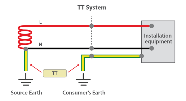
TT power supply system The TT method refers to a protective system that directly grounds the metal housing of an electrical device, which is called a protective earthing system, also called a TT system. The first symbol T indicates that the neutral point of the power system is directly grounded; the second symbol T indicates that the conductive part of the load device that is not exposed to the live body is directly connected to the ground, regardless of how the system is grounded. All grounding of the load in the TT system is called protective grounding. The characteristics of this power supply system are as follows.
At present, some construction units use the TT system. When the construction unit borrows its power supply for the temporary use of electricity, a special protection line is used to reduce the amount of steel used for the grounding device. Separate the newly added special protection line PE line from the working zero line N, which is characterized by:
TN power supply system TN mode power supply system This type of power supply system is a protection system that connects the metal housing of the electrical equipment with the working neutral wire. It is called the zero protection system and it is represented by TN. Its features are as follows.
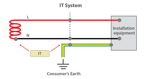
working principle In the TN system, the exposed conductive parts of all electrical equipment are connected to the protective line and connected to the ground point of the power supply. This ground point is usually the neutral point of the power distribution system. The power system of the TN system has one point that is directly grounded. The exposed electrically conductive part of the electrical device is connected to this point through a protective conductor. The TN system is usually a neutral-grounded three-phase grid system. Its characteristic is that the exposed conductive part of the electrical equipment is directly connected to the grounding point of the system. When a short circuit occurs, the short-circuit current is a closed-loop formed by the metal wire. A metallic single-phase short circuit is formed, resulting in a sufficiently large short-circuit current to enable the protective device to act reliably to remove the fault. If the working neutral line (N) is repeatedly grounded, when the case is short-circuited, part of the current may be diverted to the repeated grounding point, which may cause the protection device to fail to operate reliably or to avoid the failure, thereby expanding the fault. In the TN system, that is, the three-phase five-wire system, the N-line and the PE-line are separately laid and insulated from each other, and the PE line is connected to the housing of the electrical device instead of the N-line. Therefore, the most important thing we care about is the potential of the PE wire, not the potential of the N wire, so repeated grounding in a TN-S system is not a repeated grounding of the N wire. If the PE line and N line are grounded together, because the PE line and N line are connected at the repeated grounding point, the line between the repeated grounding point and the working ground point of the distribution transformer has no difference between the PE line and the N line. The original line is the N line. The neutral current that is assumed is shared by the N line and the PE line, and part of the current is shunted through the repeated grounding point. Because it can be considered that there is no PE line on the front side of the repeated grounding point, only the PEN line consisting of the original PE line and N line in parallel, the advantages of the original TN-S system will be lost, so the PE line and N line cannot be Common grounding. Due to the above reasons, it is clearly stated in the relevant regulations that the neutral line (ie N line) should not be grounded repeatedly except for the neutral point of the power supply. IT system IT mode power supply system I indicate that the power supply side has no working ground, or is grounded at high impedance. The second letter T indicates that the load side electrical equipment is grounded. The IT mode power supply system has high reliability and good security when the power supply distance is not long. It is generally used in places where no blackouts are permitted, or places where strict continuous power supply is required, such as electric power steelmaking, operating rooms in large hospitals, and underground mines. The power supply conditions in underground mines are relatively poor and the cables are susceptible to moisture. Using the IT-powered system, even if the neutral point of the power supply is not grounded, once the device is leaking, the relative ground leakage current is still small and will not damage the balance of the power supply voltage. Therefore, it is safer than the neutral grounding system of the power supply. However, if the power supply is used for a long distance, the distributed capacitance of the power supply line to the earth cannot be ignored. When a short-circuit fault or leakage of the load causes the device case to become live, the leakage current will form a path through the earth and the protection device will not necessarily act. This is dangerous. Only when the power supply distance is not too long is it safer. This type of power supply is rare on the construction site. The meaning of the letters I, T, N, C, S
In an electrical network, an earthing system is a safety measure that protects human life and electrical equipment. As earthing systems differ from country to country, it is important to have a good understanding of the different types of earthing systems as the global PV installed capacity continues to increase. This article aims at exploring the different earthing systems as per the International Electrotechnical Commission (IEC) standard and their impact on the earthing system design for Grid-Connected PV systems. Purpose of Earthing Earthing systems provide safety functions by supplying the electrical installation with a low impedance path for any faults in the electrical network. Earthing also acts as a reference point for the electrical source and safety devices to correctly work. Earthing of electrical equipment is typically achieved by inserting an electrode into a solid mass of earth and connecting this electrode to the equipment using a conductor. There are two assumptions that can be made about any earthing system:
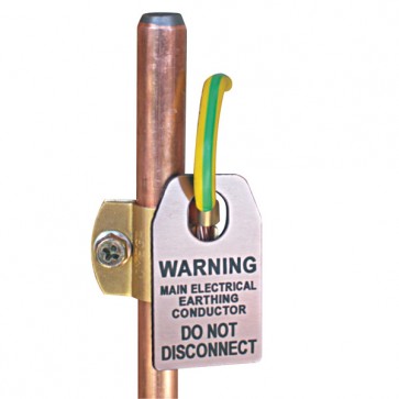
Protective Earthing Protective earthing is the installation of earthing conductors arranged to reduce the likelihood of injury from an electrical fault within the system. In the event of a fault, the non-current carrying metal parts of the system such as frames, fencing and enclosures etc. can achieve high voltage with respect to earth if they are not earthed. If a person makes contact with the equipment under such conditions, they will receive an electric shock. If the metallic parts are connected to the protective earth, the fault current will flow through the earth conductor and be sensed by safety devices, which then safely isolate the circuit. Protective earthing can be achieved by:
The protective earthing conductor should be able to carry the prospective fault current for a duration that is equal to or greater than the operating time of the associated protective device. Functional Earthing In functional earthing, any of the live parts of the equipment (either ‘+’ or ‘-‘) may be connected to the earthing system for the purpose of providing a reference point to enable correct operation. The conductors are not designed to withstand fault currents. In accordance with AS/NZS5033:2014, functional earthing is only permitted when there exists a simple separation between the DC and AC sides (i.e. a transformer) within the inverter. Types of earthing configuration Earthing configurations can be arranged differently at the supply and load side while achieving the same overall outcome. The international standard IEC 60364 (Electrical Installations for Buildings) identifies three families of earthing, defined using a two-letter identifier of the form ‘XY’. In the context of AC systems, ‘X’ defines the configuration of neutral and earth conductors on the supply side of the system (i.e. generator/transformer), and ‘Y’ defines the neutral/earth configuration on the system’s load side (i.e. the main switchboard and connected loads). ‘X’ and ‘Y’ can each take the following values:
And subsets of these configurations can be defined using the values:
Using these, the three earthing families defined in IEC 60364 are TN, where the electrical supply is earthed and the customer loads are earthed via neutral, TT, where the electrical supply and customer loads are separately earthed, and IT, where only the customer loads are earthed. TN earthing system A single point on the source side (usually the neutral reference point in a star-connected three-phase system) is directly connected to the earth. Any electrical equipment connected to the system is earthed via the same connection point on the source side. These types of earthing systems require earth electrodes at regular intervals throughout the installation. The TN family has three subsets, which vary by method of segregation/combination of earth and neutral conductors. TN-S: TN-S describes an arrangement where separate conductors for Protective Earth (PE) and Neutral are run to consumer loads from a site’s power supply (i.e. generator or transformer). The PE and N conductors are separated in nearly all parts of the system and are only connected together at the supply itself. This type of earthing is typically used for large consumers who have one or more HV/LV transformers dedicated to their installation, which are installed adjacent to or within the customer’s premises.
TN-C: TN-C describes an arrangement where a combined Protective Earth-Neutral (PEN) is connected to the earth at the source. This type of earthing is not commonly used in Australia due to the risks associated with fire in hazardous environments and due to the presence of harmonic currents making it unsuitable for electronic equipment. In addition, as per IEC 60364-4-41 – (Protection for safety- Protection against electric shock), an RCD cannot be used in a TN-C system.
TN-C-S: TN-C-S denotes a setup where the supply side of the system uses a combined PEN conductor for earthing, and the load side of the system uses a separate conductor for PE and N. This type of earthing is used in distribution systems in both Australia and New Zealand and is frequently referred to as multiple earth-neutral (MEN). For a LV customer, a TN-C system is installed between the site transformer and the premises, (the neutral is earthed multiple times along this segment), and a TN-S system is used inside the property itself (from the Main Switchboard downstream). When considering the system as a whole, it is treated as TN-C-S.
In addition, as per IEC 60364-4-41 – (Protection for safety- Protection against electric shock), where an RCD is used in a TN-C-S system, a PEN conductor cannot be used on the load side. The connection of the protective conductor to the PEN conductor has to be made on the source side of the RCD. TT earthing system With a TT configuration, consumers employ their own earth connection within the premises, which is independent of any earth connection on the source side. This type of earthing is typically used in situations where a distribution network service provider (DNSP) cannot guarantee a low-voltage connection back to the power supply. TT earthing was common in Australia prior to 1980 and is still used in some parts of the country. With the TT earthing systems, an RCD is needed on all AC power circuits for suitable protection. As per IEC 60364-4-41, all the exposed conductive parts that are collectively protected by the same protective device shall be connected by the protective conductors to an earth electrode common to all those parts.
IT earthing system In an IT earthing arrangement, there is either no earthing at the supply, or it is done via a high impedance connection. This type of earthing is not used for distribution networks but is frequently used in substations and for independent generator-supplied systems. These systems are able to offer good continuity of supply during operation.
Implications for PV system earthing The type of earthing system employed in any country will dictate the kind of earthing system design required for Grid-Connected PV systems; PV systems are treated as a generator (or a source circuit) and need to be earthed as such. For example, countries employing the use of a TT type earthing arrangement will require a separate earthing pit for both DC and AC sides due to the earthing arrangement. In comparison, in a country where TN-C-S type earthing arrangement is used, simply connecting the PV system to the main earthing bar in the switchboard is enough to meet the requirements of the earthing system. Various earthing systems exist throughout the world and a good understanding of the different earthing configurations ensures PV systems are earthed appropriately.
www.bennypass.it |

+(39) 347 051 5328
Italy - Kazakhstan


09.00am to 18.00pm
About
We offer the best and economical solutions, backed by 27+ years of experience and international standards knowledge, echnological changes, and industrial systems.
Our Services
Marketing Materials


Marketing Materials1


