
Control valve Introduction Control valves are elements used in process control loops to adjust process variables such as flow, liquid levels, pressure, temperature etc. Control valves essentially consist of a valve and an actuator; more valve control elements may also be present in certain cases. The operation of a control valve involves positioning its movable part (the plug, ball or vane) relative to the stationary seat of the valve. The purpose of the valve actuator is to accurately locate the valve plug in a position dictated by the control signal. There are several ways of providing this actuation, below list of the most used ones:
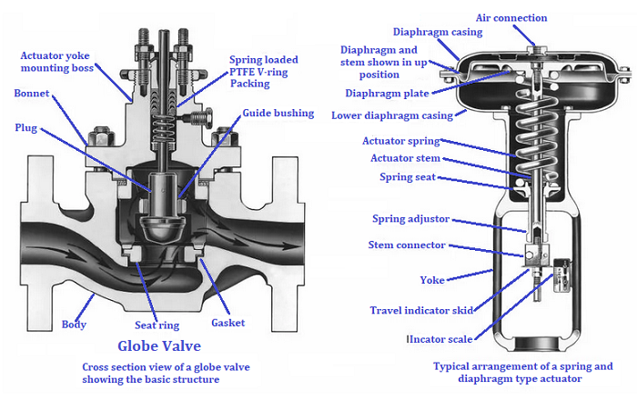
In most cases, an actuator is driven by a pneumatic positioner by an electric motor, or even self-controlled (self-regulator). Internal parts of the control valve These valves achieve the desired controlling effect essentially by throttling the flow. Figure 1 below shows details
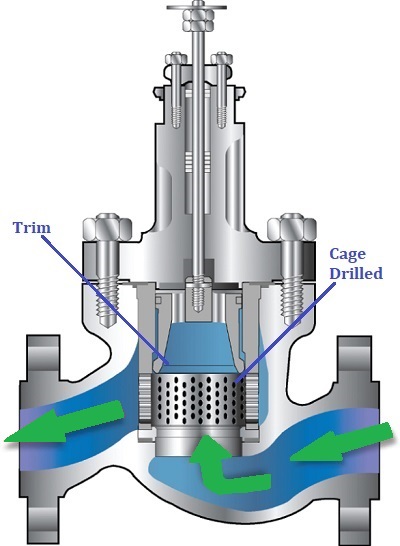
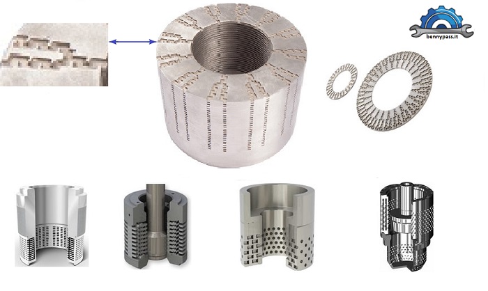
Undoubtedly the most used is the globe valve, as in Figure 1 above, and the other one has an internal cage drilled and a trim which flows inside this cage and closes or opens the holes according to the required flow rate, For more details see Figure 2 below.
There are many other types (we will see them later). Figures 1 and 2 are the most widely used.
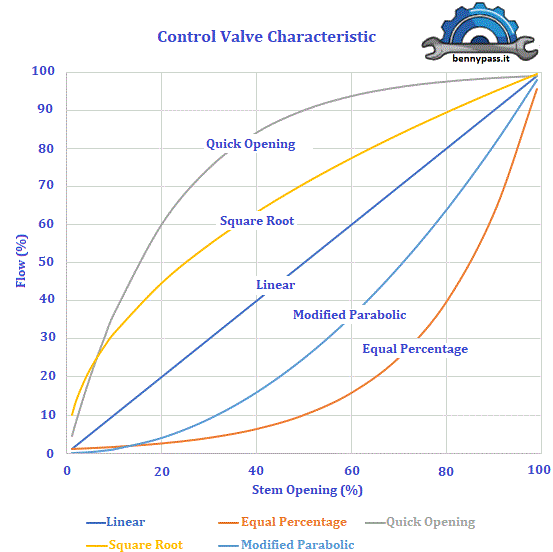
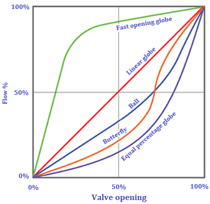
Control valve characteristic The most common characteristics are shown in the figure above. The percent of flow through the valve is plotted against the valve stem position. The curves shown are typical of those available from valve manufacturers. These curves are based on the constant pressure drop across the valve and are called inherent flow characteristics. Figure 3 below shows the different curves with each other.
Most control applications are with valves with linear, equal-percentage, or modified-flow characteristics.
Applications It is essential to correctly size a control valve for the application so that the process works effectively and efficiently. A control valve should be selected according to the application flow requirement, not the line size it is installed in. General rules: How do you decide which valve control to use? Here are some rules of thumb Linear Characteristics:
Equal Percentage Characteristics:
Quick Opening Characteristics:
Two rules of thumb for choosing the right flow characteristic:
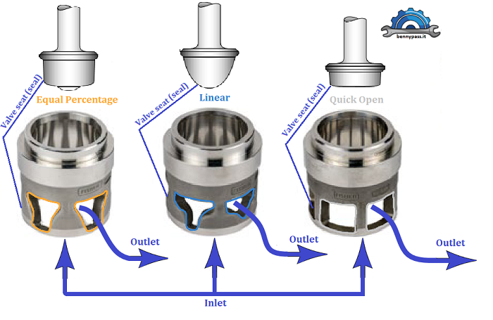
Globe Control valve Comparing linear and equal percentage valves, a linear valve might have a 25% valve opening for a certain pressure drop and flow rate, whilst an equal percentage valve might have a 65% valve opening for exactly the same conditions. The orifice pass areas will be the same. The physical shape of the plug and seat arrangement, sometimes referred to as the valve ‘trim’, causes the difference in valve opening between these valves. Typical trim shapes for spindle-operated globe valves are shown in Figure 4 In this Module, the term ‘valve lift’ is used to define valve opening, whether the valve is a globe valve (up and down movement of the plug relative to the seat) or a rotary valve (lateral movement of the plug relative to the seat). Rotary valves (for example, ball and butterfly) each have a basic characteristic curve, but altering the details of the ball or butterfly plug may modify this. The inherent flow characteristics of typical globe valves and rotary valves are compared in Figure 5
Anti Vibration-Cavitation control valve Control valves equipped with noise-abatement trim, such as a drilled-hole cage or a tortuous path stack, are typically oriented in the flow-to-open direction. This orientation maximizes noise attenuation by allowing the expanding gases to exit the valve trim and continue downstream without re-converging through the valve’s seat ring, as would happen if the flow direction were reversed Control valve vibration may be caused by many factors, some generated internally by the process stream and others generated externally. Some of the different forms of flow-induced vibration are explained below.
The last generation of Cage control valves is equipped with a labyrinth cage to avoid residual vibration. For more details, see Figure 7 below
The cage is built up with many disks superimposed with each other; of course, the diameter and number of the disks depend on the CV valve. Created this type of structure to avoid eroding and vibrations to a minimum possible. Regarding the vibration and eroding, in addition to the four points mentioned above, there is another problem that is sometimes not considered, the valve working out of the permitted limit due to the increase in production Most corrosion and vibration problems are caused by the internal CV valve, which is incorrect. Unfortunately, this happens when the valve works on the limit of pressure and flow. The relationship of DP between the inlet and outlet of the control valve is most important. Figure 8 shows a curve of the control valve from the manufacture which always must be followed and never exit from this curve, this is the reason why the datasheet of the control valve is mandatory.
CV calculation The Kv coefficient defines the water flow (between 5 ° and 40 °), resulting in m3 / h, which passes through a valve with differential pressure (pressure drop) of 1 bar. Valves are tested by running water through it before publishing the Cv value. It can be assumed that the tests are done with water (unless otherwise noted), using a specific gravity of 1.0, 1.2 centistoke viscosity, and a standard temperature of 60 degrees Fahrenheit, below the Cv = Q * √ (SG/ΔP) (units in US GPM, psi) where:
All control valves have a rated flow capacity expressed as the Cv rating. The valve flow coefficient (Cv) is the number of US gallons per minute of 60 degrees Fahrenheit water that will pass through a fully open valve with a 1 psi pressure drop. For example, a Hi-Flow™ valve with a Cv rating of 10.75 will pass 10.75 gallons per minute of water with a pressure drop of 1 psi across the valve Flow factor (Kv) is the metric system equivalent of the flow coefficient (Cv). They are also referred to as the International System of Units (abbreviated as SI system). It is defined as the flow of water in cubic meters per hour (m³/hr) at a pressure drop of one bar with a temperature ranging from 5 to 30 degrees C. Kv = Q * √ (SG/ΔP) (units in m3/hr, bar) where:
The Flow Factor (Kv) should not be misunderstood with the Discharge Coefficient (k). Discharge Coefficient (k) is a characteristic non-dimensional factor of a valve used to calculate flow that discharges from a tank to the environment. To select the proper valve for the application, it is necessary to calculate the needed flow capacity (Cv). The necessary Cv will be dependent upon the pressure drop across the valve. The greater the pressure drop taken across the valve, the greater the flow through the valve. The amount of pressure drop which should be taken depends on the specific application and the pressure available. The required application Cv is calculated with different formulas according to the medium type (e.g., liquid, gas, or steam). For Gas, use the equation shown with Cv dependent upon upstream pressure, downstream pressure, pressure drop taken, volumetric flow rate needed, temperature, and specific gravity. The relationship between CV and KV is: Cv = 1.156 * Kv or Kv = 0.864 * Cv The flow rate for a liquid Q = Cv * Sq. Root of ( ΔP/SG)
Unit conversions from Imperial to Metric (vice versa):
Conversion of units of Cv to Kv:
Conversion of units of Kv to Cv:
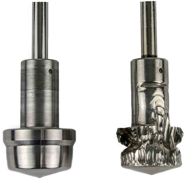
To save time from cursed calculations, below there are automatic table calculations for CV and KV, including conversion flow and pressure conversions CV and KV calculator The coefficient of Cv The coefficient of Cv is used by Engineers to size valves. In layman’s terms, you need a big enough hole for the liquid to go through. If the hole is too small, you can get a pressure drop that makes your liquid drop below its vapour pressure. If your liquid drops below its vapour pressure there will get implosions that damage the valve trims, causing wear. It is called Cavitation. In effect, the actual flow rate begins to deviate from what is predicted using the flow coefficient equation for sizing control valves. This is because the vapour bubbles occupy more volume as the mass of liquid expands during the phase change, creating an additional resistance to flow. The vapour bubble formation in the restriction prevents the flow from increasing any further. The effect is called Choked flow. Conclusion Our recommendations are never to install a valve smaller than the flow rate, but not too big either. The calculation must be done with extreme precision according to production requirements. Installing a valve with a smaller CV than the flow rate could be a hazard. Figure 8 below shows what happens when the CV of the valve is smaller than the flow rate
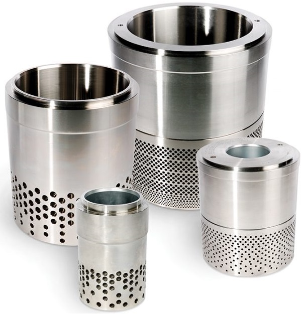
As you can see from the Figure above, the internal trim of the valve is fully destroyed We suggest never to use a control valve that works above 50% but below. Above 50% should be temporary, practically to get the liquid down quickly from a tank or other. Figure 9 below shows the internal cage of the control valve
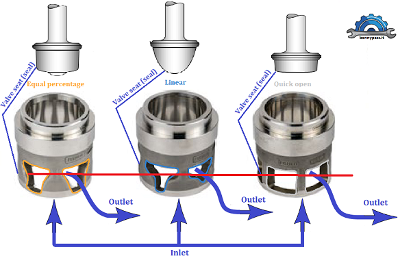
As you can see from the Figure above, the holes in the basket get bigger and bigger as the valve opens. Therefore a perfect flow rate is when the valve works with small holes. Figure 10 shows the traditional control valve
As you can see from the figure above, the red line shows how a regulating valve that reaches 50% or 60% no longer has any difference in the internal orifice, perhaps from linear becomes a quick opening. This is why a regulator valve must always work below 50% and never above For any help, you can contact the website via mail. We will get back to you as soon as possible, also for urgent situations, call the telephone number on the website. We also supply the valves according to your requests
|


+(39) 347 051 5328
Italy - Kazakhstan


09.00am to 18.00pm
About
We offer the best and economical solutions, backed by 27+ years of experience and international standards knowledge, echnological changes, and industrial systems.
Our Services
Marketing Materials


Marketing Materials1


