
Choke valve Introduction Choke valve, sometimes also known as 'choker valve', is a type of control valve, mostly used in oil&gas production wells to control the flow. Another purpose that the choke valves serve is to kill the pressure from the reservoir and regulate the downstream pressure in the flowlines. Choke valves allow fluid flow through a tiny opening designed to kill the reservoir pressure while regulating the wellhead production. The reservoir fluids can contain sand particles. Hence the choke valves are usually designed to handle an erosive service. Typical configuration in oil&gas producing wells has two choke valves in series, one non-regulating choke valve and one regulating choke valve. Of course, the non-regulating choke valve must be the first one connected to wells and then regulating the choke valve. Design Standards The principal design standards for the oil and gas industry are given below. A. American Petroleum Institute (API)/International Organization for Standardization (ISO)
The pressure rating up to 20000 PSI These standards cover all aspects of design, performance, materials, welding, qualify control, equipment marking, storage and shipping and qualification and have specific requirements for related equipment including choke valves and their actuators. Choke Valve Working Principle The choke valve is similar to the cut-off valve in appearance and structure. Therefore, the parts of the choke valve and the cut-off valve are highly interchangeable. The choke valve is very similar to the cut-off valve in appearance and structure. The only difference between them is the shape of the disc and the working stroke. Therefore, the parts of the choke valve and the cut-off valve are highly interchangeable. The are several models of choke valves. Below the list
Let's say that the most used are 1, 2, 4, 5. Below the characteristic Rotating disk choke valve
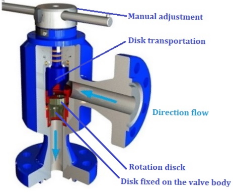
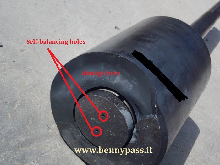
This type of valve has two perforated discs superimposed on each other. When the two holes of the two discs coincide, the flow rate is maximum; of course, when they are on opposite sides, the passage is closed. Depending on the diameter of the holes, the maximum flow rate is calculated. Figure 2 below shows the internal movement of the choke valve.
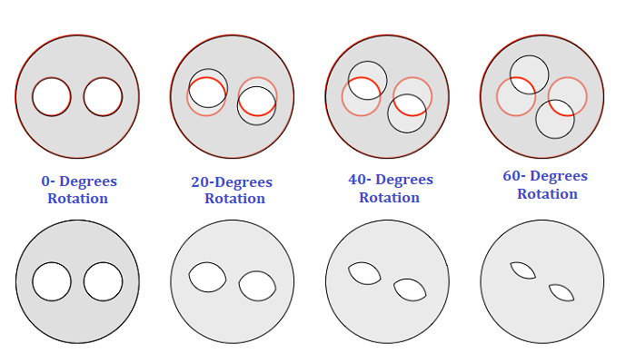
As you can see from Figure 2 above, the disk that moves is only one; the other is fixed on the valve body Valve trim is being built of Solid Tungsten carbide, of course, is a very strong material suitable for stones and sand. The figure above shows the name of the company (QUAM). They are the leader of choke valves. Italy Platforms use only this type of valves, which are very reliable. Suppose these valves are not subjected to external agents such as vibrations or corrosion due to the continuous use of corrosive substances such as chemicals. In that case, these types of valves (QUAM) can last up to 20 years. In addition to effectively regulating well flows, this type of valve is the absolute best for controlling the injection of chemicals up to 20,000 PSI without any problems. We always recommend the company QUAM, which is the absolute leader for Rotating Disk Choke Valves. Figure 3 below shows the position of the disks when the valve is fully open (0 degrees) till 60 degrees (closing direction)
There are also other companies like DRAG or Cameron that provide discs in ceramic which is suitable for the hydrous and chemical or better for corrosive substances, but not for the sand. While the Solid Tungsten carbide is ideal for the sand, it also can be considered is suitable for the hydrous and chemical but not like the ceramic. However, based on our experience, if needed, a choke valve that keeps closing the passage fully when the valve itself is closed, i.e. when the holes of the two discs are in the opposite direction, the ceramic disks are the best. As per Figure 1 above, the lever manually controls the valve opening or closing. It is possible by request to apply an actuator for operating the valve in auto. For more details contact technical support on the website. Plug & Cage Choke Valve
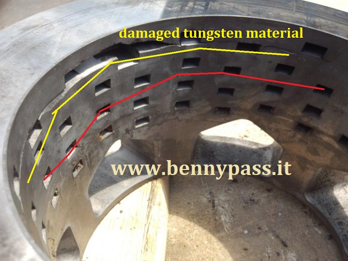
This type of latest generation valve has been designed to avoid vibrations, cavitations, and corrosion to the minimum possible. In fact, the internal cage is made up of many overlapping discs with labyrinths. The internal labyrinths avoid resonance where the flow is very high. In a plug and cage choke valve, the plug is used as the controlling element, and throttling of the flow happens on the internal diameter of the ported(?) cage. The flow enters the choke inlet and circulates around the annulus between the body and the cage in a flowing scenario. So that it is possible to achieve the most appropriate combination of controllability and flow capacity for each application, the ports in the cage are sized and arranged in a specific manner. An important consideration when sizing the choke valve is the ability to achieve closely managed well startup while also optimizing capacity for the end of wellhead life to maximize production. This is why the correct choice of the cage with the appropriate size is very important when designing a plug and cage valve for specific applications. The plug and cage choke valve incorporate the largest possible flow area, making it a great choice for high flowrate applications. These types of choke valves are also constructed with the plug tip and inner cage of material solid tungsten carbide for better resistance to erosion. The plug and cage choke valves are available in manually operated or actuated models. Specifications and features
External Sleeve & Cage (Choke valve)
External-sleeve-style choke valves are one of the most widely accepted and conventional trims used thought the oil and gas industries. External sleeve chokes are designed to provide accurate flow control throughout its operating range. The externally guided sleeve controls the opening and rate of flow. The flow is directed upward away from the outlet, impinges on itself in the centre of the flow cage, which isolates the body bore from incoming turbulent flow, eliminating the body wear and making it ideal for low capacity/high-pressure drop applications. Due to its unique design, the trim also offers superior erosion protection for formidable pressure drop operations with heavy sand concentrations. Relocating the throttling element to the outside of the cage increases the trim’s annulus area, which in turn reduces the risk of premature erosion and failure caused by a high-velocity flow. An increased 'gallery' provides homogenous flow distribution around the trim, reducing localised wear on the central cage and decreasing body erosion. The pressure-balanced self-flushing ports located on the sleeve reduce the stem load on the valve, thus reducing the required actuator force to operate the valve. Pressure-balanced seals increase adjustability while minimising the necessary sealing forces required for the valve to maintain an ASME Class IV leakage rate. Usually, the seat is metal to metal. It is located on the bottom of the slave, which separates with flow path, safeguarding its positive shut-off sealing ability while also increasing the valve's service life. This option is one of the best things about this type of valve As a result of the trim being constantly present within the flow path, the control surfaces can be subjected to acceleration non-uniform wear. Therefore, it is highly recommended to utilise hard-faced or tungsten-carbide sealing elements when operating this trim in erosive and/or corrosive applications when operating this trim.
Specifications and features
Needle Choke Valve
Needle Spline trims are the perfect solution for low-flow-rate and high-pressure-drop choking applications. Needle Spline trims are commonly used for methanol injection, to prevent hydrate formation by reducing the temperature drop across the choke. Needle (trims) can be subject to clogging and build-up if used with highly viscous fluids or if particle sizes are greater than the internal passageways. Due to trim constantly being present within the flow path, the control surfaces can be subjected to accelerated wear. It is strongly recommended to utilise hard faced or tungsten-carbide sealing elements when using this trim in erosive and corrosive applications like H2S or sand. Also, consider the design of needle a balanced spindle is required, and therefore typically requires larger actuator forces compared to other trims.
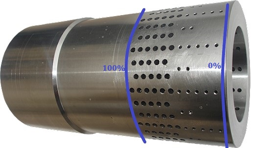
Common Problem Unfortunately, the choke valves, even if they are excellent for regulating pressure and flow from the wells, the choke valves are also classified as sacrificial valves. They withstand everything that comes from the wells, such as sand or even stones if the wells' filter is damaged. When buying a valve, it is essential to consider pressure, the density of liquid or gas or both, and the maximum flow rate. In each application, the mixture of fluids will be unique to the individual operating environment and will change over time as production continues. For example, when the well is nearing the end of his life, could be an increase of water (also sand) in the production and cause the change of density in output, so inside the choke valve. all these things could lead to increases in vibrations, erosions, and even corrosion of the valve itself. We recommend always before buying a choke valve should be clarified at first if possible interchange the internal parts according to the density without replacing the body valve, especially when the valve is welded on the pipes. To avoid increased erosion or corrosion, including vibrations, we recommend buying a valve that can work in normal production below 45-50% opening. It has been found that the wear increases when the valves are working above 50% on many choke valves. If we take a cage of any company as a reference, the diameters of the holes change, for example, when the valve is open at 25%, or it is open at 50%. Figure 7 below show this difference
It should be noted that surface choke valves are rarely mounted vertically, contrary to popular belief. They are much more likely to be mounted so that flow arrives from the side. Subsea chokes valve can be installed As you can see from Figure 7 above, the cage holes change between 0% and 100%. When a valve works between 30-32%, its regulation is much more accurate than the valve works to 48-50%. If the valve works with the smaller holes, it is much more stable. The next and last problems of choke valves are described below
Erosion It is essential to understand the difference between single and two-phase scenarios. For two-phase, this is 10-15 m/s and for gas 25 - 40 m/s. It should also be noted that often choke valves are reduced in size, for example, a 4-inch nominal body with 6-inch inlet and/or outlet flanges. Suppose the velocity at the outlet flange is still within the rule mentioned above. In that case, it does not automatically indicate that everything will be expected to work fine, as the velocity in the so-called nominal body goes up and may well exceed what is considered to be acceptable. The choke velocity should be calculated first of all with the same body and flange size before reducing the nominal body size. If the velocity is lower than mentioned in the above rule of thumb, one can calculate a smaller nominal body with a smaller flange. If still within the given limits, a smaller body with larger flanges can be used to reduce erosion risk. Therebefore, velocity is the most critical design criteria; correct design limitation of this in combination with a well-designed trim will limit any erosion. Calculating velocities must be based on general calculations for gas, liquids and a combination (two-phase). An analysis is required to determine the necessary Cv. We can achieve this by fitting different trims in nominal body sizes. However, different pipe diameter selection produces different velocities. Relatively low velocities are not advised. As a result, it is likely to select a too-large size choke. High velocities are likely to result in body erosion with an associated high maintenance cost. Trim selection is also essential. For example, there are chokes valves equipped with a cage provided with holes uniformly distributed over the entire circumference. This design ensures that the fluid is symmetrically distributed. The many flow jets are opposed (diametrically). Consequently, the energy is dissipated in the centre of the valve. This occurs in the fluid itself and not near the surface of any choke component. Also, preferential flow, the major cause of body erosion, is fully avoided. Ultimately, when valves are purchased, they always arrive too big or too small. The reason is simple, wrong calculations and valve out of specification. Remember, when buying a valve, everything must be considered:
These parameters are of fundamental importance (Erosion is the main problem of vibration) Flashing and cavitation The vibration may shatter brittle materials. This is the reason why the Tungsten Carbide is often used for the trim. Let's start with the symptoms that lead to cavitation of a valve What is the choke flow If the inlet pressure (P1) and valve flow area are fixed, the flow through a valve will normally rise as the downstream pressure (P2) is reduced. The “Ideal” line in figure 8 illustrates this point, showing how liquid flow increases linearly when charted against the square root of the differential pressure across the valve divided by specific gravity.
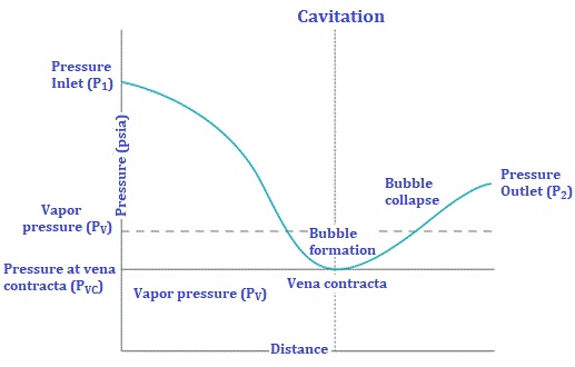
Figure 8 shows the flow rate through a valve rises as the pressure drop across the valve increases. In reality, the maximum flow will be limited due to choked flow conditions. Actuality, the maximum liquid flow through the valve can never exceed a choked flow limit, and at this point, the flow will increase no further, no matter how low the P2 pressure is reduced. A similar phenomenon occurs with valves in gas service. If the P1 pressure and flow area remain fixed, flow through the valve will rise as P2 is reduced, but at some point, choking will begin to occur, and the flow will rise no higher, regardless of the value of P2. Why does choked flow occur? In liquid applications, choking results from reducing pressure through the control elements. Figure 9 shows the instantaneous pressure as liquid moves through a control valve. The valve's inlet and outlet cross-sectional areas are much larger than the control area, such as the cage or the area around the plug and seat. Because the total flow at any location in the valve is the same, the liquid velocity in the reduced area (vena contracta) must be much higher to pass the same flow.
Figure 9 shows a typical pressure curve of a cavitating liquid passing through a control valve. If P2 is reduced still further, the expanding vapor will increase pressure drop and eventually limit flow. By Bernoulli’s law, the total energy at every point in the flow stream is constant, so if velocity is increased, pressure must fall. As the fluid passes through the restriction, it speeds up, lowering the pressure at that point. Once the liquid enters the much larger outlet piping, the flow rate slows, and some pressure is recovered. This pronounced pressure dip becomes more dramatic as flows are increased. If the instantaneous pressure in the vena contracta falls below the vapor pressure, then vapor bubbles will begin to form as the liquid begins to boil. The conversion to vapor increases the volume of the fluid and begins to restrict flow. If the downstream pressure is lowered still further, the vapor volume will increase to the point that flow throughput can increase no further, regardless of how low the downstream pressure is reduced. This condition is called choked flow. In gas applications, the vapor velocity through the valve will increase until the vapor reaches sonic velocity. At this point, the vapor can go no faster because of standing shock waveforms and limits flow. Further reduction of the downstream pressure will have no effect on flow through the valve. Choked vapor flow conditions are very common in relief valves and control valves with very high flows, but can also occur in high-velocity flare headers at piping transitions. Choked flow is also common in vacuum systems, because the low air pressures found in these systems greatly reduce the speed of sound, increasing the likelihood of standing shock waves. Choked flow misconceptions and issues Choked flow by itself does not generally damage a valve, but there are flow conditions commonly associated with the choked flow that can create problems, including: Noise levels: Choked flow does not directly create noise, but high noise can result from process phenomena normally associated with the choked flow. In liquid systems, cavitation can be present during choked flow, which creates noise and can ultimately damage the valve. As downstream pressure is reduced, cavitation transitions to flashing. While cavitation can have a high sound pressure level due to the implosion of the collapsing vapor bubbles from micro-jets and shock waves, flashing will have reduced noise due to the resulting two-phase flow. In vapor flow, the noise will rise significantly as the velocity turns sonic. As the downstream pressure is reduced, the extra energy is converted to sound energy. Valves with excessive pressure drop can generate sound levels greater than 100 dB. With either liquid or vapor flows, the overall level of noise is usually related to the differential pressure across the valve. When choking first appears, the noise will be present but may not be excessive. As the downstream pressure falls, the noise will increase dramatically and can damage valve internals and subject operators to unsafe sound levels. Flashing and cavitation: A common misconception is that choked flow conditions require flashing conditions, but choked flow can occur under cavitating conditions as well. As shown in figure 9, cavitation will result when the P2 pressure rises above the vapor pressure of the liquid. When this occurs, the bubbles collapse and turn back into liquid. If the P2 pressure remains below the vapor pressure, the liquid will boil and flash to vapor as it passes through the valve and remain a vapor as it exits (figure 10).
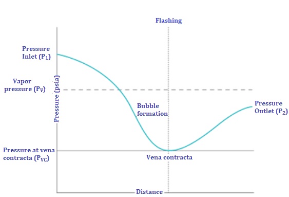
Figure 10 shows a typical pressure curve of a flashing liquid passing through a choke valve. Fluid enters the valve as a liquid and exits as a vapor. Incipient cavitation will not usually result in fully choked flow. However, as cavitation becomes more pronounced, the flow will begin to choke, and the overall flow will deviate from the ideal flow curve as shown in figure 8. The level of cavitation (and extent of choking) is dependent on the properties of the liquid; the process pressure, temperature, and flow; the inlet and outlet piping; and the specific construction and parameters associated with the valve itself. Flashing may or may not indicate choked flow. If the valve differential pressure is high, the P2 pressure is well below the vapor pressure, and the flow is low, the flow through a valve could be flashing but not choked.
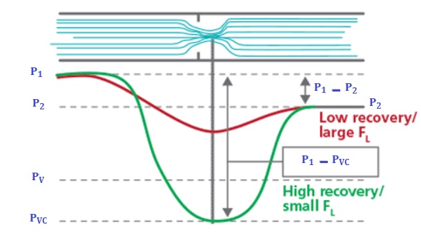
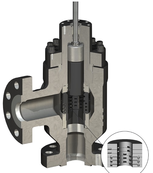
Valve damage due to choking: Users often assume choked flow conditions will damage the valve. However, there are times when a valve is choked and the damage is minimal, and there are times when the valve is not choked and the rate of damage is significant. Cavitation can ultimately damage a valve. As the bubbles collapse, they form microjets and create localized shock waves that erode valve internals and downstream piping. As discussed above, cavitation can occur without necessarily fully choking the valve flow. Flashing conditions can create valve damage as well, but this is typically less pronounced than cavitation damage and is usually worse at very low valve openings when the valve flow is probably not choked. As the valve opens further, the flow may become choked, but the valve damage will likely be reduced as the plug moves away from the seat. Figure 11 shows a graph that compares the vena contracta pressures of a high recovery (ball, butterfly) valve versus a low recovery (globe) valve for the same process conditions. A high recovery valve creates significantly lower internal pressures, increasing the likelihood of cavitation. Excessive noise can also damage the valve due to high vibration and metal fatigue. As discussed earlier, the amount of noise generated varies significantly based on process conditions, so the noise may not be directly associated with flow choking. Cavitation, flashing, and noise damage can be alleviated and even eliminated by specifying appropriate valve body designs, special valve trims, and materials of construction (figures 11 and 12). Low recovery valves (such as globe valves) generate a much less pronounced pressure dip as the flow passes through, so cavitation is reduced. Special anti-cavitation trims (figure 5) can reduce the risk of cavitation damage even more by either further minimizing the pressure dip, or by directing the cavitating liquid into the centre of the flow passage to minimize damage to the valve internals and walls. Hardened alloys can be used for critical valve internal components to reduce damage caused by flashing or cavitation. Noise can be significantly reduced by using low noise trims, inlet and outlet noise attenuators, or downstream modal noise attenuators. Valve sizing: Calculating a choked flow scenario is based upon process conditions and flowing media parameters for a given valve position. The fact that a valve is choked for a unique combination of parameters does not mean it cannot pass more flow, as an increase in flow can often be obtained by increasing the Cv of the valve. Software programs are available to predict choked flow conditions and estimate the maximum flow, as described in the subsequent section.
Figure 12 Figure 12. Special valve trims, such as the DRAG 100 DPG trim, can be employed to attenuate noise, reduce cavitation, or direct cavitating liquids away from valve components—all of which minimize damage to the valve. Predicting choked flow Many valve vendors have control valve sizing programs that can predict choked flow conditions and help users size the valve correctly. However, these programs are only as accurate as of the input data, so the correct process and valve information must be entered. The presence and extent of flow choking depend on many process conditions, including the physical properties of the fluid involved, flow rates, upstream and downstream pressures, process temperature, and inlet and outlet piping configurations as well as a number of details associated with the control valve itself. Special parameters, such as pressure drop ratio, pressure recovery factor, and cavitation index, help predict exactly when cavitation or choking will occur, and how much flow a valve will pass. Because the parameters for each body style and trim are different, each option must be evaluated individually to determine the actual flow that can be safely passed under a specific set of process conditions. Such sizing calculations can become complicated, especially when several trim options are available, so it is wise to consult your valve vendor to help evaluate options and determine the best solution for your application. Valve selection Choked flow, in and of itself, is not a cause for concern. The confusion stems from the association of choked flow with many negative phenomena that can affect and damage control valves. When faced with the possibility of choked flow, or if there are concerns or questions about how to proceed with valve sizing or selection, contact valve vendors for technical support. They can usually provide valve sizing programs that predict when choking will occur and its impact on valve sizing and selection. They can also help users choose the best combination of materials and trim designs to alleviate damaging conditions. For any questions, you can contact us here on the website, a specialized team will answer you as soon as possible
Cavitation damage prediction The concern with cavitation is twofold: high noise levels and the potential for valve damage. Several reliable methods exist for predicting valve noise, including methods published by the International Electrotechnical Commission, the ISA and the German VDMA. No standard exists for predicting cavitation damage. A common misconception is that choked flow conditions require flashing conditions, but choked flow can occur under cavitating conditions as well. As shown in figure 9, cavitation will result when the P2 pressure rises above the pressure of the liquid. When this occurs, the bubbles collapse and turn back into liquid. If the P2 pressure remains below the pressure, the liquid will boil and flash as it passes through the valve and remain as it exists (figure 9). Figure 13 and 14 below shows what happens if the calculations are not considered or are made wrong. This valve suffered tremendous cavitation due to different densities.
Leaking The selection of incorrect materials sometimes causes leaks on Choke Valves but may also be attributed to Choke Valve's general design. Some chokes have a split body design. These vary from a forged block (main body) with weld-on or fitted flange connections (adapters) to the main body bolted bonnet type. A one-piece body casting is one answer to these problems. Also, the Choke Valve seals have to fail before leaks occur. Seals utilised on almost all designs are of the O-Rings type. As a choke is used under high pressure and pressure drop, these O-Rings may be subjected to explosive decompression. This can cause them to split or deform. Should this happen, the sealing property is lost. Explosive decompression often occurs when Viton is used. This happens to be one of the most suitable resilient materials for hydrocarbon service. Hence careful consideration of seal materials is required if Viton is selected as it is subject to explosive decompression. Furthermore, the service of the O'Rings has to be considered as this can differ from static to dynamic applications. Most problems with O'Rings occur in dynamic applications.
Conclusion Choked flow, in and of itself, is not a cause for concern. The confusion stems from the association of choked flow with many negative phenomena that can affect and damage control valves. When faced with the possibility of choked flow, or if there are concerns or questions about how to proceed with valve sizing or selection, contact valve vendors for technical support or you can contact our team here on the website. They can usually provide valve sizing programs that predict when choking will occur and its impact on valve sizing and selection. They can also help users choose the best combination of materials and trim designs to alleviate damaging conditions.
Recommendations
|


+(39) 347 051 5328
Italy - Kazakhstan


09.00am to 18.00pm
About
We offer the best and economical solutions, backed by 27+ years of experience and international standards knowledge, echnological changes, and industrial systems.
Our Services
Marketing Materials


Marketing Materials1


