
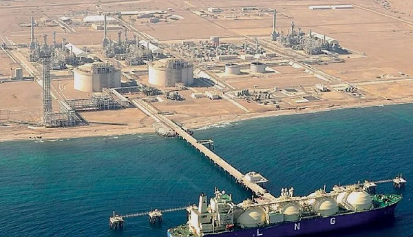
Ground tanks and LNG storage systems As part of an LNG refuelling system, primary storage facilities or simpler satellite systems must be provided. The primary storage plants are generally divided into various sections: storage, unloading, boil-off vapour recovery, bunkering and truck loading (MISE, 2015). For LNG storage, special tanks are used, specially built under conditions that the LNG must be stored. From this point of view, it is customary to distinguish "onshore" tanks located at ports or in specific fixed refuelling stations (Figure 1) from "on-board" tanks, such as those used by LNG ships or LNG-powered vessels. In this article, considering the tanks on land as those on board ships will be dealt with in report 2. In this article, consider the tank on land (onshore) as those on board ships will be dealt with in the next article.
note1: External tanks can be steel and concrete, combining the two. The standard does not deal with internal tanks made exclusively of prestressed concrete.
Figure 1. LNG storage systems in the port area: graphic example (Oman daily observer 2019) The choice of the ground tank type to be used depends on a diversity of elements, such as the example below.
For ground tanks, it is usual to use mainly two solutions (DNV, 2015b):
Flat bottom tanks Flat bottom tanks are usually used when the volumes to be stored are quite high (over 10,000 m3), and storage occurs at atmospheric pressure. For large tanks, the choice of atmospheric pressure is quite common since it reduces costs for maintaining the pressure itself and for resistance requirements of the materials, which are less stringent (STAVROS, 2016). Typically this type of tank is equipped with steam management systems, and from an empirical point of view, a daily vaporisation value of about 0.05% is considered acceptable (DNV, 2015b). This type of ground tank presents the problems associated with the "rollover" phenomenon, which is the phenomenon that occurs when layers of liquid are formed at a temperature and, therefore, different densities inside a tank. The heated underlying liquid decreases its density, causing the abrupt mixing of the various layers and the consequent evaporation of a quantity of LNG that could be excessive for release through the safety valves. This can lead to cracks forming in the tanks or other damage due to the pressure developed. The rollover phenomenon is generally avoided by using liquid handling systems or filling systems at various tank heights. For on-board installations, rollover is much less likely, given the natural shuffling of the cargo as the ship moves. Steam management becomes fundamental in atmospheric pressure tanks such as typically flat bottoms. Practically, it is possible to use four different solutions (Munko, 2007; DNV, 2015b), as shown below:
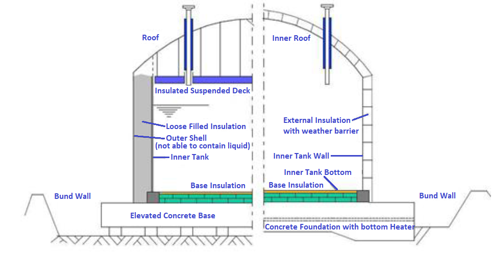
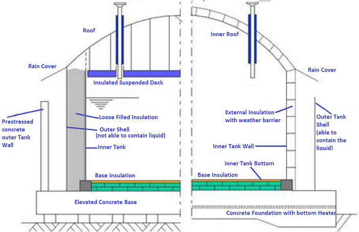
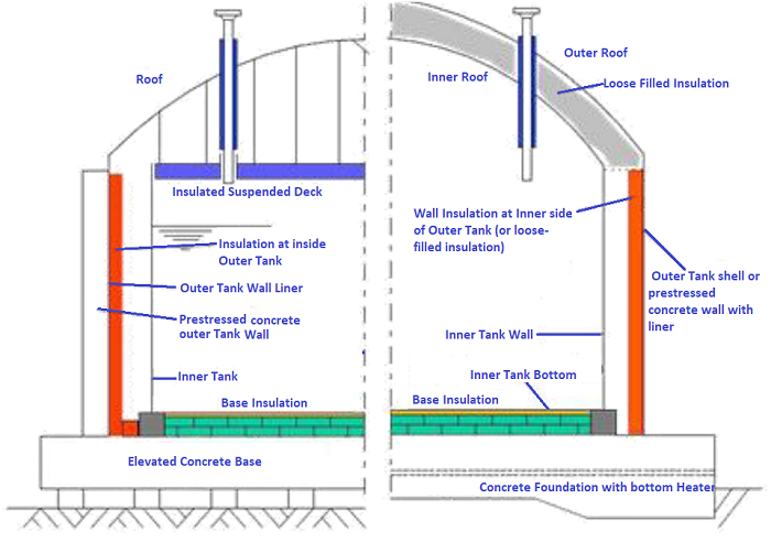
There are three main containment methods in the context of flat bottom tanks, as shown below.
Regarding the containment systems, specifications are provided in dimensions to balance the need for control of dispersions in the liquid phase with the opportunity not to limit the vaporisation of the released product. These specifications differ because the containment systems relate to satellite tanks or distribution plants (see note 2) In the case of large LNG terminals, vast quantities of liquid to be stored may be required. For such situations, it is possible to use multiple flat bottom tanks, possibly also with modular solutions that allow the necessary infrastructural investments to be spread over time. Note 2: In the case of satellite tanks (ground installations with storage capacities between 5 and 50 t), must provide a containment system with a volume of 2 m3 and a minimum surface area of not less than 2 m2 to contain any limited losses of LNG. In this case, the system represents a containment area in the shape of an underground vessel or delimited by walls or by the land's topography. The height of the walls possibly used for the construction of the containment system must be such as not to prevent the intervention of the fire brigade. Must seal any openings for the passage of pipes.
Cylindrical tanks ("bullet tanks") The second type of ground tank widespread internationally is of bullet tank, used if one wishes to use pressurised tanks. This type of tank is typically designed to withstand pressures up to 7 bar and is equipped with pressure relief valves. Generally, the capacity of these tanks is between 500 and 6,000 m3 (the typical volume is 1,000 m3), so when the overall storage capacity required is high, and it is intended to store large quantities of LNG, it is necessary to use more tanks. Cylindrical. The main materials used for this type of tank are steel with a 9% nickel or stainless steel (AISI 304 type). Insulation is obtained through the vacuum solution, perlite, glass wool, and polyurethane (DNV, 2015b). Factors that influence the capacity of the tanks In carrying out the refuelling procedure, it is essential to consider the factors that affect the filling capacity of the tanks to ensure that the activities are carried out in complete safety. As is known, they include:
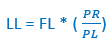
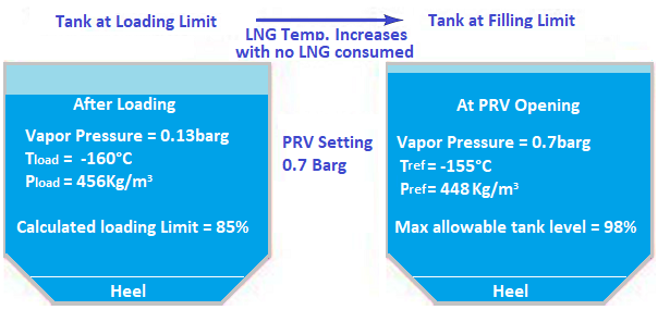
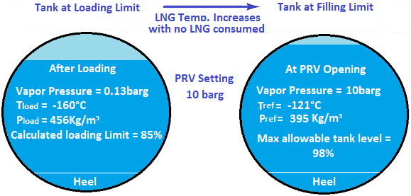
Where: LL is the loading limit, FL is the filling limit, ρR is the density at the reference temperature, ρL is the density at the loading temperature. Typical values range from 85% to 95% depending on the tank type, the pressure value set in the relief valves, etc. During the completion of refuelling operations, it is essential to evaluate these factors' effects. Generally, inside the tanks, although they can be isolated, there is the formation of a certain amount of vapour, which will be in equilibrium with the liquid. However, as the heat continues to penetrate through the insulation, the density of the liquid tends to decrease due to the temperature increase. Consequently, the space available to steam, especially when the tank is almost fully, decreases further, causing an increase in the vapour pressure. If the rise is out of control, it will reach the relief valve's limit value. At that moment, the LNG temperature will be equal to the reference one. It is necessary to consider two other factors:
|


+(39) 347 051 5328
Italy - Kazakhstan


09.00am to 18.00pm
About
We offer the best and economical solutions, backed by 27+ years of experience and international standards knowledge, echnological changes, and industrial systems.
Our Services
Marketing Materials


Marketing Materials1


