
Working principle of Rotary Vane Pumps A Vane pump is a positive displacement pump used to increase the pressure of the flowing fluid by using a vane mounted on a rotor. This pump can flow fluid from one point to another at high pressure. Van pumps may have variable lengths of vans or tensioned to maintain the van’s contact with the pump wall as the vans rotate. Charles C. Barne invented the vane pumps in 1874.
Vane pumps operate via the positive displacement principle, also known as a rotary vane or sliding vane pumps. Positive displacement pumps move the fluid by trapping a fixed volume and forcing that trapped fluid into the discharge pipe. As its name would suggest, vane pumps have rectangular-shaped vanes mounted into slots on a rotor that turns inside the asymmetrical pump casing. As the rotor turns, the asymmetrical shape casing will cause the vanes to move in and out of the slots to touch the casing walls. In this case, the fluid will trap between this and the rotor. This mechanism draws the fluid around until it forces out of the discharge port. There are mainly three types of vane pumps:
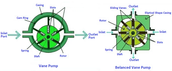
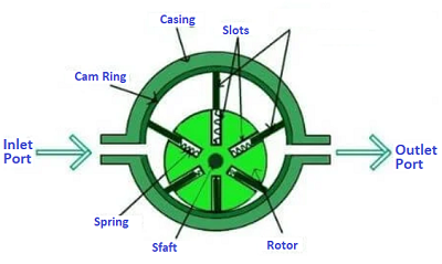
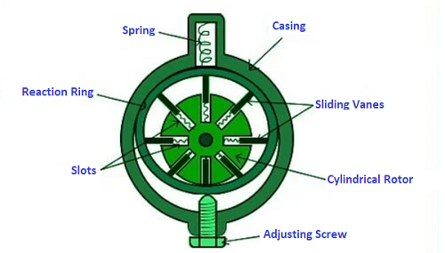
Figure 1 below shows all details of Vanes Pump
Figure 1. Vanes Pump Drawing
1. Unbalanced Vane Pump
Unbalanced vane pumps are the regular vane pump you have read about in this article. It consists of a cylindrical rotor mounted on an offset inside a circular casing. This means that the center of the cylindrical rotor and the center of the casing is not coincidental. The center of the casing and the rotor centres are at some distance. There is no leakage between the vane tips and the casings. Two inlets are present on opposite sides of each other, and two outlets are present on opposite sides of each other. Due to thises type of arrangement of inlets & outlets, equal and opposite thrust is balanced, and therefore no side thrust is experienced by the rotor shaft. Balanced Vane Pump
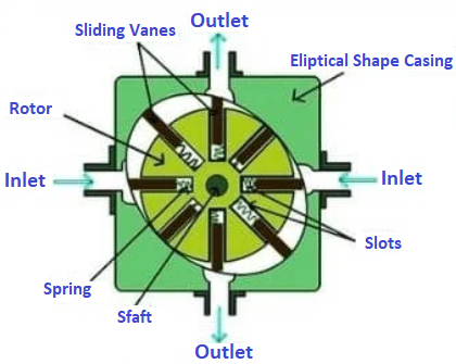
In balanced vane pumps, the casing is elliptical in shape. The center of the rotor and elliptical casing is the same, and no offset is used. For equilibrium, two inlets and two outlets are provided, due to which no pressure difference is created between the inlet and the outlet. Two inlets are present on opposite sides of each other, and two outlets are present on opposite sides of each other. Due to thises type of arrangement of inlets & outlets, equal and opposite thrust is balanced, and therefore no side thrust is experienced by the rotor shaft. A balanced pump gives better service and longer life. The pocket size between the two vans increases when moving from the outlet to the outlet, and the pocket size decreases when moving from the inlet to the outlet. Therefore the inlet port has suction, and the outlet port has a delivery. Variable Displacement Vane Pump
In a variable displacement vane pump, the pocket-size can be varied. Due to different pocket sizes, the discharge from the outlet varies. In this variable displacement vane pump, the casing is not in direct contact with the casing. A ring is provided between the casing and the pane, and this ring is called the reaction ring. On one side, the feedback ring is connected with the adjustment screw, and on the other side, it is connected with a spring. The adjusting screw is used to separate the pocket size of this pump. By turning the adjustment screw, the reaction ring can be moved upward or downward. By moving the reaction ring up or down, the offset between the reaction ring center and rotor center. As the offset change, the pocket size also changes, & hence the discharge from the pump changes.
Vane Pump Working First, the power provided to the shafts of the pump get by an electric motor. After giving power, the shaft starts rotating, & the rotor mounted on the shaft also starts rotating. When the rotor rotates, the sliding vans present in the rotor slot undergo a centrifugal force that is radially direct outwards. Due to the centrifugal forces on the sliding vane, the vans move outward, and the spring that connects the rotor and vane expands. Then the springs expand, and the sliding vans contact the cam-ring. This contact will remain in this condition until the rotor stops (rotates). When the vane reaches a position where the distance between the rotor shaft and the casing is short, it will compress the springs of the vanes to maintain contact with the cam ring. In this case, the area between the two adjacent vans and the casing is also smaller, i.e., the pocket size is smaller. Similarly, when the vane reaches a position where the distances between the rotor shaft and the casing are large, the spring of the vanes expands to maintain contact with the cam-ring. In this case, the area between the two adjacent vans and the casing is also larger. When the rotors rotate continuously, suctions are formed in the inlet port after some time, which causes the fluids to suction into the inlet port. The fluid which sucked through the inlet gets trapped between two adjacent vans, & as the vanes are always in contact with the cam-rings, the trapped fluid rotates along with the two adjacent vans. While moving from the inlet ports to the outlet port, the fluid experiences a centrifugal force that increases the pressure of the fluid, & this high-pressure fluid, is transported through the outlet port to the required area. Near the inlet vane pumps, increase the space between the two adjacent vans due to the increasing distance between the shaft and the casing. As the space between two adjacent vans increases, a vacuum will create near the inlet of the vane pump. Due to the vacuum created, suction starts and will take fluid from the pump’s inlet. After that, as the rotors continue to rotate, the compression of the fluid continues to rotate, and the space between the adjacent vans begins to decrease, i.e., the pocket-size decreases. As the pocket size decreases, the fluid volume decreases, the entangled fluid becomes narrower, and the fluid pressure increases. After that, the high-pressure fluids will discharge from the vane pump outlet. Working Principle of Vane Pump The schematic of the vane pump’s working principle is shown in the figure. Vane pumps generate a pumpings action by tracking the vane along the casing wall. In the vane pump, the rotor is connected to the prime mover via a shaft. Vans are located on a slotted rotor. The rotor is placed eccentrically inside a cam ring, as shown in the figure. The rotor is sealed in the cam by two side plates. When the prime mover rotates the rotors, the van is thrown outward due to centrifugal force—Van tracks along the ring. This provides the fluid with a tight hydraulic seal that is higher at higher rotation speeds due to higher centrifugal force. This produces suction cavities in the ring as the rotor rotates. This creates a vacuum at the inlet, and, therefore, the fluid is pushed into the pump through the inlet. The fluid is carried around the outlet by the vanes, by which the fluid is expelled by retreating. The efficiencies of the pump depend on the eccentricity, expansion of the vanes and the width of the vanes, and the rotor speed. It may be noted that the fluid will not flow when eccentricity is zero. These pumps can handle thin fluids (low viscosity) at relatively high pressures. However, these pump is not suitable for high-speed applications and for high-viscosity liquids or liquids carrying certain viscous particles. Design benefits Little metal to metal contact – As the vanes are generally constructed from carbon graphite, there is no real metal to metal contact inside the pump. Not only does this reduce the amount of wear to the internals of the pump, which results in lower maintenance and overall running costs, it also allows the pump to handle non-lubricating fluids such as alcohols and gasoline. Versatile solution – The vane pump design is able to handle a range of low to medium viscosity clean fluids, including those at high temperatures, those with gas/vapour content and as discussed above non-lubricating fluids thanks to the little metal to metal contact. Ease of maintenance –The main wearing part within the vane pump design is the vanes themselves. As these are designed to be easily removed and replaced without any significant cost or time implications, vane pumps are generally seen as low maintenance solutions. Good suction/vacuum capabilities – Thanks to the tight seal between the vanes, rotor and pump casing, the vane pumping principle benefits from good suction capabilities making them ideal for applications such as tank stripping. Performance less affected by suction head – A vane pump, like most positive displacement pumps, is not affected by the pressure against which they operate. This is the opposite of a centrifugal pump, which is far more affected by changing suction conditions and is, therefore, a lot more likely to operate away from the desired duty point. This makes the vane pump particularly suitable for performing applications where the suction pressure may change such as tank to tank transfer. Dry run for short period times – Whilst not designed to be left to run dry, rotary vane pumps are able to run without fluid entering the pump for a short period. Typical applications of a vane pump Rotary vane pumps are a popular and efficient solution for the transfer of clean, low to medium viscosity fluids and fuels at a range of temperatures and relatively low pressures. Rotary vanes pumps are a particularly good choice for the following applications:
The sliding vane pump design makes them generally unsuitable for high viscosity applications, as a thick liquid would prevent the vanes from moving in and out of their slots with ease. In addition, their very tight tolerances mean that solids cannot pass and will jam the vanes; hence them being suited to relatively clean liquids. Vane pumps tend to be used in low-pressure installations rather than high pressure. As the pressure within the pump chamber increases, the vanes start to struggle to maintain contact with the casing walls and push the fluid around. Components of Vane Pump Casing The cover vane is the outer covering of the pump. All other components of the vane pumps are present inside this casing. The wrapper has two casings:
Shaft Inside the vane pump is a shaft that is connected to a prime mover. A rotor is mounted on the shaft, & it rotates using the power of the prime movers. Rotor The rotor of the vane pumps has slots that are equally spaced around the rotor. This rotor has various radial slots. Sliding Vanes Slot vans are present in the slot of the rotor. Sliding vans move freely inside the rotor slots. The sliding vans are rectangular-shaped and are attached using a spring with the rotor. Cam Ring The cam ring is present on the inner wall of the casing. Advantages of Vane Pump
Disadvantages of Vane Pump
Troubleshooting vane pumps Rotary vane pumps are a robust and reliable design, yet as with anything, issues can occur. Should you experience a problem there is a likely explanation which can be identified using the below troubleshooting table.
|


+(39) 347 051 5328
Italy - Kazakhstan


09.00am to 18.00pm
About
We offer the best and economical solutions, backed by 27+ years of experience and international standards knowledge, echnological changes, and industrial systems.
Our Services
Marketing Materials


Marketing Materials1


