
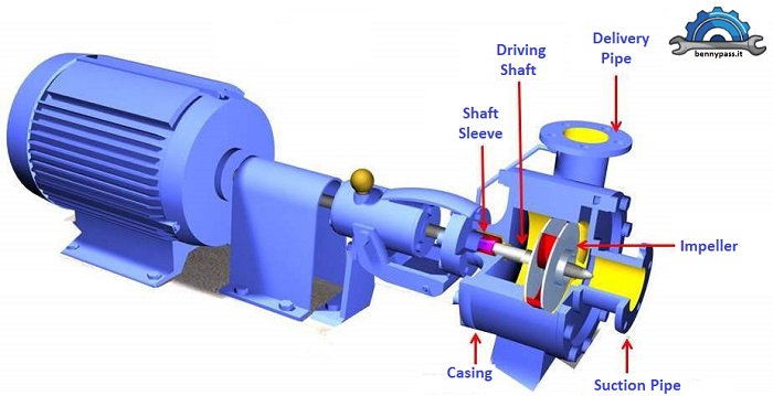
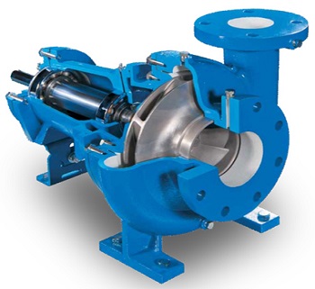
Working principle of Centrifugal Pump It is one of the exciting and straightforward topics in fluid mechanics. What is the need for a pump? We require a pump to transmit water from a region of low pressure to a part of higher pressure. The centrifugal pump is one of the most popular pumps ever. The pump uses a centrifugal force acting on the liquid surface to convert the mechanical energy. The centrifugal pump flows in a radial outward direction. Therefore the pump works like a reverse reaction turbine. These pumps raise the water or liquid from a lower level to a higher level. A centrifugal pump definition is a hydraulic machine that converts the mechanical energy into hydraulic energy through a centrifugal force acting on the fluid. What is a Centrifugal Pump? A Centrifugal pump is a mechanical machine that pumps the fluids by converting the mechanical power (rotational energy) into the pressure energy of the fluid flow. The electric motor or engine generally supplies this mechanical power. A centrifugal pump uses a centrifugal force to pump the fluids. Therefore, it is known as a centrifugal pump. It is the simplest type of hydraulic equipment used in various industries and in many everyday appliances to move fluids from low to high-pressure areas. It uses an impeller to pump the fluid or water from one location to other. In 1475, engineer Francesco Di Giorgio Martini designed a centrifugal pump as a mud lifter device. Figure 1 below shows a traditional centrifugal pump.
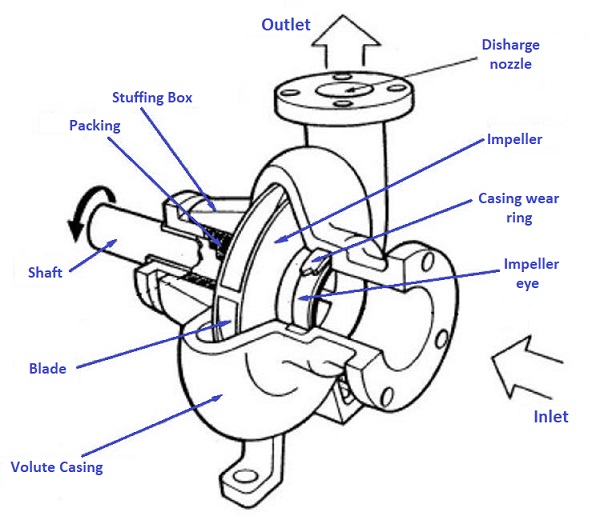
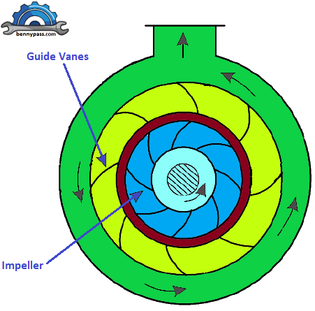
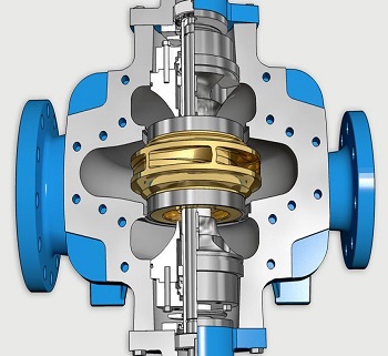
These dynamic pumps are mostly used in the food and chemical industries to pump viscous liquids efficiently. These pumps are cheaper than positive displacement pumps. In simple words, it is a brilliant pump that can work efficiently in different applications. Centrifugal pumps are very common all over the world industries. The main reason for their popularity is that these pumps have no power loss due to friction. This dynamic pump has a simple design and is very easy to control. They don’t have leakage and heat transfer problems. For this reason, they get preference over the positive displacement pump. Figure 2 below shows the internal details of the Centrifugal Pump.
Types of Casings in Centrifugal Pump
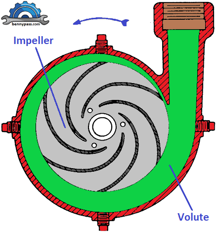
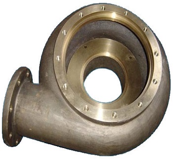
Volute casing (Spiral casing) - The impeller surrounds it. Such a casing provides a gradual increase in the flow area, thus decreasing the water velocity and correspondingly increasing the pressure. Figure 3 below shows a Volute Casing.
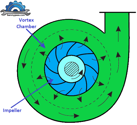
Figure 3. Volute Casing Vortex casing - A vortex casing is a circular chamber introduced between the impeller and casing. Here the fluid from the impeller has to first pass through the vortex chamber and then through the volute casing. In such a case, a better conversion has done that is velocity energy into pressure, and it has good efficiency than the volute casing. The vortex chamber converts some of the kinetic energy into pressure energy. The volute chamber further increases the pressure energy. Thus the efficiency of a volute pump fitted with a vortex chamber is more than that of a simple volute pump. Figure 4 below shows a Volute Casing.
Casing with guide blades - In this type of casing, the runner surrounds with the help of a different number of guide blades. These blades attach around a ring that is known as a diffuser. The design of guide blades doesn’t affect the water exiting the impeller as it enters the diffuser. As the area of these blades increase, the water velocity reduces and its pressure energy increase. Mostly, the casing remains concentric with the impeller. Figure 5 below shows a Casing with Guide Blades.
Machines with diffuser blades have a maximum efficiency but are less satisfactory when a wide range of operating conditions is required. These pumps are costlier than volute pumps.
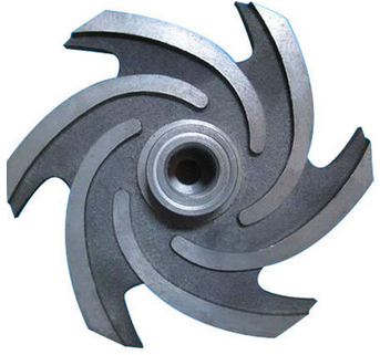
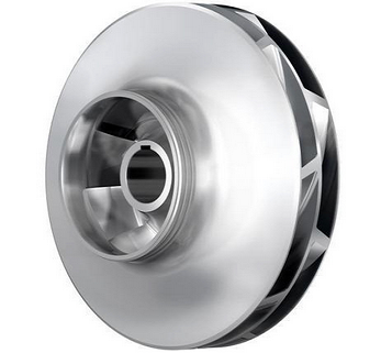
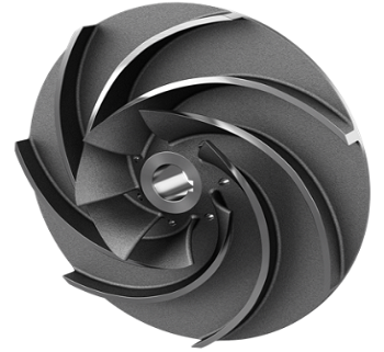
Wet End Components The wet end of the pump includes those parts that determine the pump's hydraulic performance. The two primary wet ends are the impeller and casing (Impeller). The impeller is a rotor used to increase the flow's kinetic energy. There are several models of Impeller, each with its characteristics. The table below shows these details. The impeller blades can be
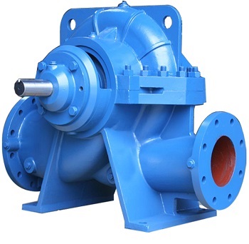
Single or Double suction Impellers In a single-suction centrifugal pump, water flows into the pump inlet, and 100% of the liquid immediately flows into the eye or inlet of the impeller. The centrifugal action creates pressure as the water exits the impeller through the veins. The significant difference between a single and double suction pump is the latter has an impeller designed to draw flow through it from both sides. This double suction design splits the flow inside of the pump and sends 50% of the water through two “eyes.” This splitting or double suction design eliminates the axial forces on the impeller, which allows for higher flows than single suction pumps. Figures 12 and 13 show the casing difference between single and double suction Centrifugal Pump. See the differences between the inlet and outlet of flange connections on both casings.
Multi-Stage Centrifugal Pumps
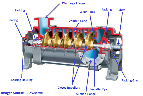
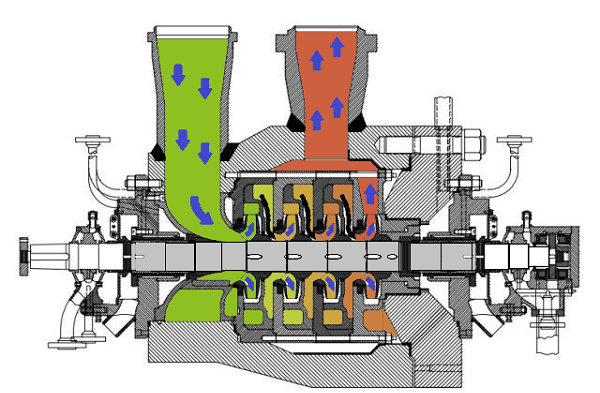
A centrifugal pump with a single impeller that can develop a differential pressure of more than 150 psid between the suction and the discharge is difficult and costly to design and construct. A more economical approach to producing high pressures with a single centrifugal pump is to include multiple impellers on a common shaft within the same pump casing. The internal channels of the pump (casing) route the discharge of one impeller to the suction of the other Impeller till the last Impeller (series). Figure 17 shows a diagram of the impellers with a four-stage pump. The water enters the pump from the top left and passes through each of the four impellers in series, going from left to right. The water goes from the volute surrounding the discharge of one impeller to the suction of the next impeller.
Mechanical End Components The mechanical end includes those parts that support the impeller within the casing. The mechanical end of the pump consists of the pump shaft, sealing, bearings and shaft sleeve, Suction pipe & delivery pipe. So let's see what they are
Classification of Centrifugal Pump Classification of the Centrifugal Pumps is in several ways. Below are all the details.
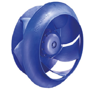
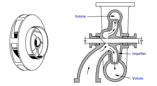
Note1: Radial Flow Pumps - In a radial flow pump, the liquid enters at the center of the impeller and is directed out along the impeller blades at the right angle to the pump shaft. The impeller of a typical radial flow pump and the flow through a radial flow pump are shown in Figure 18 below.
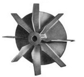
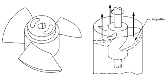
Note 2: Axial Flow Pumps - In an axial flow pump, the impeller pushes the liquid parallel to the pump shaft. Axial flow pumps are sometimes called propeller pumps because they operate essentially like a boat's propeller. The impeller of a typical axial flow pump and the flow through a radial flow pump are shown in Figure 19 below.
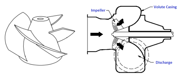
Note 3: Mixed Flow Pumps - Mixed flow pumps borrow characteristics from both radial flow and axial flow pumps. When the liquid flows through to the impeller of a mixed flow pump, the impeller blades push the liquid away from the pump shaft and the pump suction at an angle greater than 900. The impeller of a typically mixed flow pump and the flow through a mixed flow pump are shown in Figure 20 below.
Operating Principle of Centrifugal Pumps In this section, we will discuss how a centrifugal pump operates. Centrifugal pumps work to produce flow or raise a fluid from a lower level to a higher level. In base on a straightforward mechanism is the working principle of these pumps. A centrifugal pump turns rotational energy from a motor into energy in a moving fluid. The two main components responsible for this task are the impeller, and the casing, which belongs to the portion of the pump called the wet end. The impeller is the rotating part, and the casing is the airtight path surrounding the impeller. The fluid in a centrifugal pump enters the casing, falls on the "impeller vanes" at the impeller eye, and rotates radially outward until it exits the impeller through the diffuser (volute). The casing as passes through the impeller, the fluid gains both velocity and pressure. Figures 21 and 22 below show precisely this process.
A centrifugal pump converts rotational energy into energy as moving fluid, often from a motor. When passing through the impeller, the fluid receives both velocity and pressure. Depending on the use in various applications, pumps are available in different capacities and sizes. You have to consider the pressure and volume required to run the pump. Another important consideration is the horsepower needed. The main parameters below affect the performance of a centrifugal pump. Consider these parameters are of fundamental importance when choosing a pump. It can be defined as the resistance to shear when energy is applied. In general, centrifugal pumps are suitable for low viscosity fluids because the pumping action produces high liquid shear.
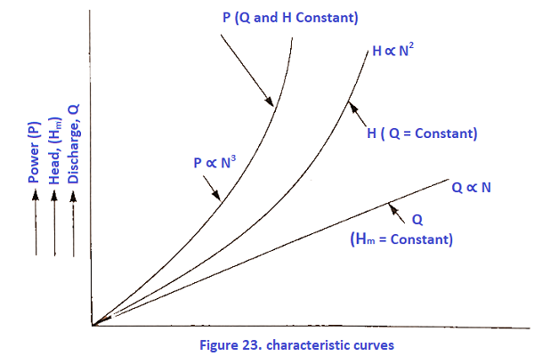
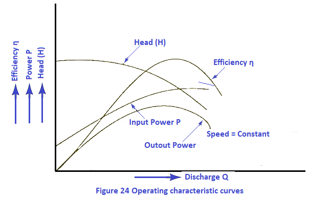
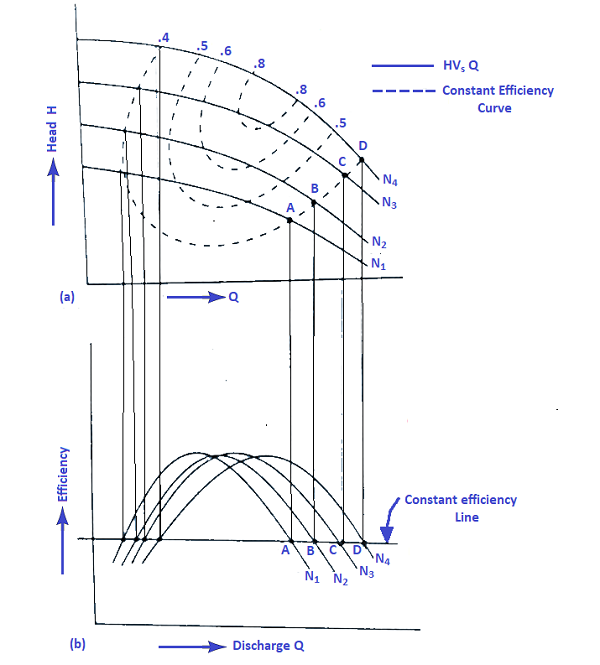
Characteristic Curves of Centrifugal Pump Characteristic curves of centrifugal pumps are defined as those curves plotted from several tests on the centrifugal pump. These curves are necessary to predict the behaviour and performance of the pump when the pump is working under different flow rate heads and speeds. The following are the essential characteristic curves for pumps :
What are the main applications for centrifugal pumps? Centrifugal pumps are commonly used for pumping water, solvents, organics, oils, acids, bases and any ‘thin’ liquids in industrial, agricultural and domestic applications. There is a centrifugal pump design suitable for virtually any application involving low viscosity fluids. The table below shows all details.
Cavitation
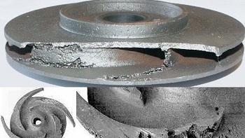
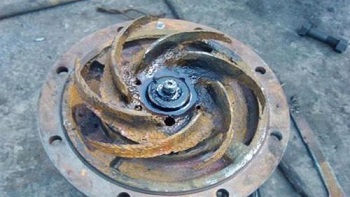
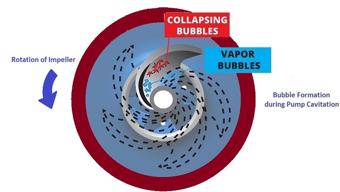
The flow area at the eye of the pump impeller is usually smaller than either the flow area of the pump suction piping or the flow area through the impeller vanes. When the liquid being pumped enters the eye of a centrifugal pump, the decrease in flow area results in an increase in flow velocity accompanied by a decrease in pressure. The greater the pump flow rate, the greater the pressure drop between the pump suction and the eye of the impeller. If the pressure drop is large enough, or if the temperature is high enough, the pressure drop may be sufficient to cause the liquid to flash to vapor when the local pressure falls below the saturation pressure for the fluid being pumped. Any vapor bubbles formed by the pressure drop at the eye of the impeller are swept along the impeller's vanes by the flow of the fluid. When the bubbles enter a region where the local pressure is more significant than saturation pressure farther out the impeller vane, the vapour bubbles abruptly collapse. This process of the formation and subsequent collapse of vapour bubbles in a pump is called cavitation. Figure 28 below shows all details. Cavitation in a centrifugal pump has a significant effect on pump performance. Cavitation degrades the performance of a pump, resulting in a fluctuating flow rate and discharge pressure. Cavitation can also be destructive to pump internal components. When a pump cavitates, vapor bubbles form in the low-pressure region directly behind the rotating impeller vanes. These vapor bubbles then move toward the oncoming impeller vane, where they collapse and cause a physical shock to the leading edge of the impeller vane. This physical shock creates small pits on the leading edge of the impeller vane. Each pit is microscopic, but the cumulative effect of millions of these pits formed over hours or days can destroy a pump impeller. Cavitation can also cause excessive pump vibration and damage pump bearings, wear rings and seals. A small number of centrifugal pumps are designed to operate under conditions where cavitation is unavoidable. These pumps must be specially designed and maintained to withstand the small amount of cavitation during their operation. Most centrifugal pumps are not designed to withstand sustained cavitation. Noise is one of the indications that a centrifugal pump is cavitating. A cavitating pump can sound like a can of marbles being shaken. Other indications observed at a remote operating station are fluctuating discharge pressure, flow rate, and pump motor current. Methods to stop or prevent cavitation are presented in the following paragraphs.
Preventing Cavitation If a centrifugal pump is cavitating, several system designs or operational changes may be necessary to increase the NPSHA above the NPSHR and stop the cavitation. One method for increasing the NPSHA is to increase the pressure at the pump's suction. For example, if a pump is taking suction from an enclosed tank, raising the liquid level in the tank or increasing the pressure in the space above the liquid increases suction pressure. It is also possible to increase the NPSHA by decreasing the temperature of the liquid being pumped. Reducing the temperature of the liquid decreases the saturation pressure, causing NPSHA to increase. Recall from the previous module on heat exchangers that large steam condensers usually subcool the condensate to less than the saturation temperature, called condensate depression, to prevent cavitation in the condensate pumps. If the head losses in the pump suction piping can be reduced, the NPSHA will be increased. Various methods for reducing head losses include increasing the pipe diameter, reducing the number of elbows, valves, and fittings in the pipe, and decreasing the length of the pipe. It may also be possible to stop cavitation by reducing the NPSHR for the pump. The NPSHR is not a constant for a given pump under all conditions but depends on certain factors. Typically, the NPSHR of a pump increases significantly as the flow rate through the pump increases. Therefore, reducing the flow rate through a pump by throttling a discharge valve decreases NPSHR. NPSHR is also dependent upon pump speed. The faster the impeller of a pump rotates, the greater the NPSHR. Therefore, if the speed of a variable speed centrifugal pump is reduced, the NPSHR of the pump decreases. However, since a pump’s flow rate is most often dictated by the system's needs to which it is connected, it can be made only limited adjustments without starting additional parallel pumps, if available. The net positive suction head required to prevent cavitation is determined through testing by the pump manufacturer and depends upon factors including the type of impeller inlet, impeller design, pump flow rate, impeller rotational speed, and the type of liquid being pumped. The manufacturer typically supplies curves of NPSHR as a function of pump flow rate for a particular liquid (usual water) in the vendor manual for the pump.
Summary Cavitation The important information in this chapter is summarised below.
Advantages of Centrifugal Pump
Disadvantages of Centrifugal Pump
Application of Centrifugal Pump
|
||||||||||||||||||||||||||||||||||||||||||||


+(39) 347 051 5328
Italy - Kazakhstan


09.00am to 18.00pm
About
We offer the best and economical solutions, backed by 27+ years of experience and international standards knowledge, echnological changes, and industrial systems.
Our Services
Marketing Materials


Marketing Materials1


