Differential Pressure Transmitter (Pneumatic Kent-Tleghl)
The pneumatic pressure transmitter is an element of the regulation circuit pneumatic that transduces the greatness to be measured. In this case, a pressure in a modulated air pressure of 3 to 15 psi. Figure 1 below shows the details.
Description and principle of functionality
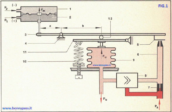 Figure 1 - Pneumatic Pressure Transmitter Figure 1 - Pneumatic Pressure Transmitter
Components:
- Measurement cell
- Inelastic membrane
- Leverage of forces
- The fulcrum of the lever (3)
- Lamina of the modulator group
- The nozzle of the modulator group
- Throttling of the modulator group
- Amplifier relay
- Reaction bellows
- Zero adjustment spring
- Auxiliary lever of the reaction bellows
- Transmission field adjustment slider
This transmitter is of the balanced-force type. The transmitter is supplied with a constant compressed air pressure of 20 psi and outputs a modulated pressure (Pu) ranging from 3 to 15 psi (depending on the differential pressure to be transmitted). The differential pressure to be transmitted (P1 - P2) is sent to a measuring cell (1).
An inelastic membrane divides this cell into two chambers (2). The highest pressure (P1) operates in a chamber (+), and in the other chamber (-), the lower pressure (P2). A force (Fm) directed upwards acts on the membrane. The greater the pressure, the greater the differential pressure (P1 - P2). The membrane is connected to the left end of the force lever (3), whose fulcrum is at point (4).
Force on the lever (3) will act as an upward force directly proportional to the differential pressure. The force F generates a moment M given by:
Fm = Fm X a
Where a is his arm, which tends to bring the lamina (5) closer to the nozzle (6) and then increase the modulated pressure from the modulator group. The pressure modulated and amplified by the relay (8) is sent to the output, and the reaction bellows (9).
The outlet pressure (Pu) generates in the reaction envelope a force (Fu) which in turn creates a moment (Fm) on the right end of the force lever (3) given by:
Fm = Fu X b
where b is its arm, which tends to move the plate away from the nozzle and decrease the outlet pressure.
The system is in equilibrium when the two moments are equal. Any unbalance involves bringing the foil closer to the nozzle and then changing the outlet pressure (Pu).
In conditions of equilibrium, we have:
Fm X a = Fu x b
Since the Fm is proportional to the differential pressure (P1 - P2) to be transmitted and the Fu is proportional to the outlet pressure (Pu), it has that at each value of the differential pressure corresponds to a well-defined value of the pressure output of the transmitter.
By varying the arm (b) of the reaction force (Fu) and moving the slider (12), the transmission range is changed. The spring (10) (zero adjustment spring) acting on the auxiliary lever (11) allows obtaining an outlet pressure of 3 psi when the differential pressure is zero.
Construction details
The instrument consists of the following fundamental parts:
- Measurement cell
- Basement
- Membrane
- Leverage of forces
- Modulator group
- Amplifier relay
- Reaction group
- Zero adjustment spring
- Zero suppression spring
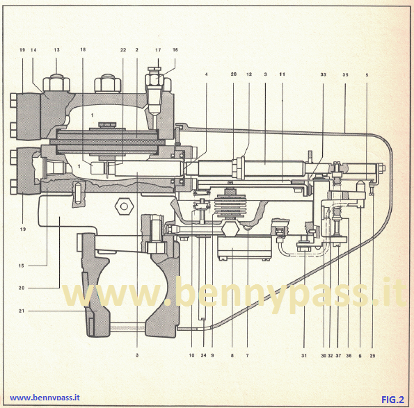
Figure 2 - Construction details
The individual parts are:
- 1. Cella di misura
- 2. Membrana
- 3. Effetto leva delle forze
- 4. Messa a fuoco della leva di forza 131
- 5. Gruppo modulatore lamella
- 6. Ugello gruppo modulator
- 7. Limitazione
- 8. Relè dell'amplificatore
- 9. Soffietti di reazione
- 10. Molla di regolazione zero
- 11. Leva ausiliaria
- 12. Cursore di regolazione del campo di trasmissione
- 13. Prigionieri della cella di misura
- 14. Corpo superiore della cella di misura
- 15. Corpo inferiore della cella di misura
- 16. Valvola di sfiato
- 17. Valvola di sfiato
- 18. Dado di bloccaggio della piastra 1221 alla leva di forza 131
- 19. Flange di collegamento
- 20. Supporto del trasmettitore
- 21. Staffa di ancoraggio
- 22. Piastra di fissaggio membrana (2) alla leva di forza (3)
- 28. Controdado del cursore di regolazione (12) della gamma di trasmissione
- 29. Vite micrometrica per la regolazione della posizione della piastra (5)
- 30. Slitta portaugello (6)
- 31. Vite slitta portaugello (30)
- 32. Vite fissaggio portaugello 1301
- 33. Fulcro della leva ausiliaria (11)
- 34. Vite regolazione molla regolazione zero
- 35. Coperchio
- 36. Molla di soppressione zero
- 37. Vite di controllo della molla di soppressione dello zero (36)
Cell Measurement
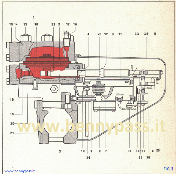
Figure 3 - Cell Measurement
Consider figure 3, which represents the entire sectioned transmitter. The measuring cell is delimited by the upper body (14) and the lower body (15) of the transmitter, joined together by the studs (13). The membrane (2) is clamped between these two bodies. The upper body and its membrane delimit the chamber - the lower body and the membrane delimit the chamber +.
The chambers are equipped with a vent valve (16) with the relative needle cap (17) (the vent valve of the chamber is not visible in the figure positive). When the process fluid is a gas, the vent valve is mounted laterally in order to allow the condensation to drain. The differential pressure connections to be transmitted to the measuring cell are made using the connecting flanges (19). The materials used to construct the measuring cell vary according to the nature of the process fluid.
Basement
The lower body (15) of the measuring cell is rigidly fixed to the base (20) of the transmitter. At the bottom of the basement below the measuring cell is fixed the anchor bracket (21). The instrument under test is designed to be mounted on a pipe in a horizontal position.
However, it is possible to mount the transmitter on a pipe in place vertically; in this case, it is necessary to calibrate it in a vertical position. Figure 4 shows the cross-section of the membrane (2)
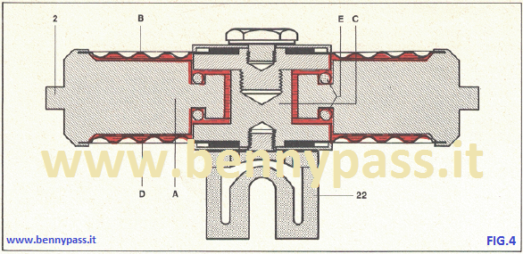 Figure 4 - Membrane of Pressure Transmitter Figure 4 - Membrane of Pressure Transmitter
- B. Diaphragms
- C. Pin
- D. Silicone oil
- E. Ring gaskets
- 2. Membrane
- 22. Diaphragm fixing plate (3) to the force lever (3)
It consists of two diaphragms (B), appropriately shaped and very thin of steel, whose outer circumference is welded to solid wood (A). In the central part of the solid wood (A), a hole is made, in which it can move a pin (C) vertically. The membrane section shows how the inner circumference of the diaphragm is fixed to the pin (C).
Silicone oil (D) is interposed between the two diaphragms and the solid wood. The oil can pass freely between the two chambers delimited by the two diaphragms. The two-ring gaskets (E) avoid irremediable permanent deformations of the two diaphragms. Where there is a large difference in pressure on the external surfaces of the two diaphragms, the pin lowering or rising meets one of the two seals and blocks communication between the two chambers. The differential pressure acting on the outer surfaces of the two diaphragms causes the movement of the pin, which in turn transmits it to the lever of the forces (3), being integral with the latter using the plate (22). The plate is fixed to the lever (3) through the nut (18) (observe the entire transmitter). The diameter of the diaphragm and the thickness of the diaphragm depends on the field transmitter transmission.
The diameter of the membrane will be greater the smaller the differential pressure to be transmitted. The membrane is made of stainless steel for high and medium differential pressures. When the differential pressure is low, it is made of polyethene (10 ± 150 mmH2O) The transmission range of the transmitter in question may vary from 0 ~ 500 to 0 - 6000 mm H2O. The maximum static pressure that can bear is 100 Kg/cm2.
Leverage of forces
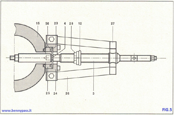 Figure 5 - Leverage of forces Figure 5 - Leverage of forces
- 3. Leverage of forces
- 4. Fulcrum of the lever of forces
- 12. Transmission field adjustment slider
- 15. Lower body of the measuring cell
- 23. Circular flexible diaphragm
- 24. Lever fixing flange (3)
- 25. Ring 26. Thrust bridle
- 27. Attacks of attack of the thrust bridle
- 28. Cursor lock nut (12)
- 56. Ring gaskets
Figure 5 on the side represents the detail of the lever of the forces (3) and its fulcrum (4). The force lever, coming out of the lower body (15), consists of two parts screwed together at the exit point from the measuring cell, consisting of the fulcrum point (4). The lever's fulcrum is made of a flexible circular diaphragm (23) of steel.
The diaphragm is tightened, in the central area, between the two parts of the lever and peripherally between the flange (24) and the ring (25). Between the diaphragm and the ring (25) and between the ring and the lower body (15), there are interposed Teflon ring gaskets (56). Therefore, the diaphragm also provides for sealing the process fluid in the measuring cell. The lever has two thrust harnesses (26) made of two flexible steel plates parallel to the base of the transmitter. The thrust bridles have one end integral to the base and the other connected to the lever's two appendices (27) (3). The external part of the force lever is threaded; in this way, it is possible to move the slider (12) of the transmission field adjustment after loosening the lock nut (28).
Modulator group
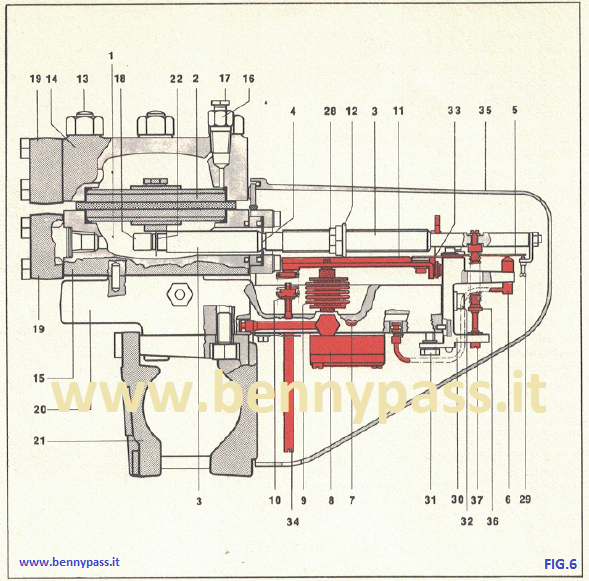 Figure 6 - Modulator group Figure 6 - Modulator group
The modulator group is of the simple type. The plate (5) is integral to the nozzle holder slide (30). Small manual corrections of its position can be made using the micrometre screw (29). The screw (29) also has the task of transmitting the displacements of the force lever to the blade (5). The nozzle (6) is fixed to the nozzle holder slide (30). The nozzle holder slide can be translated vertically relative to the base of the transmitter using the screw (31) after loosening the locking screws (32). The restriction (7) is screwed onto the base part that serves as a collecting plate.
Amplifier Relay
The relay (8) is a continuous leakage air pressure and volume amplifier (see test 4).
Reaction Group
The reaction bellows (9) has the fixed base integral with the base of the transmitter and the mobile one mechanically connected with the auxiliary lever (11). The auxiliary lever is pivoted through the cross fulcrum (33). The lengthening of the reaction bellows; therefore, the raising of the auxiliary lever is transmitted to the force lever (3) using the slider (12).
Zero Adjustment Spring
The zero adjustment spring (10), which allows obtaining at the outlet from the transmitter a pressure of 3 Psi, when the pressure to be transmitted is null, acts on the auxiliary lever (11) and is adjustable using the screw (34). To perform the zero adjustments without removing the cover, a hole is made in the lower part of the cover (35) and correspondence of this screw.
Zero Suppression Spring
The transmitter is equipped with a zero suppression spring (36). This spring, adjustable with the screw (37), allows suppressing a part of the differential pressure to be transmitted or to perform the inversion of the action of the transmitter. These two particular applications will be examined at the end of this test.
Examination
The visual examination of this transmitter can be extended to all parts that compose it. The examination makes it possible to ascertain the efficiency of each component. After visual inspection, the pre-calibration and calibration of the transmitter must be carried out.
Visual inspection of the measuring cell with its membrane
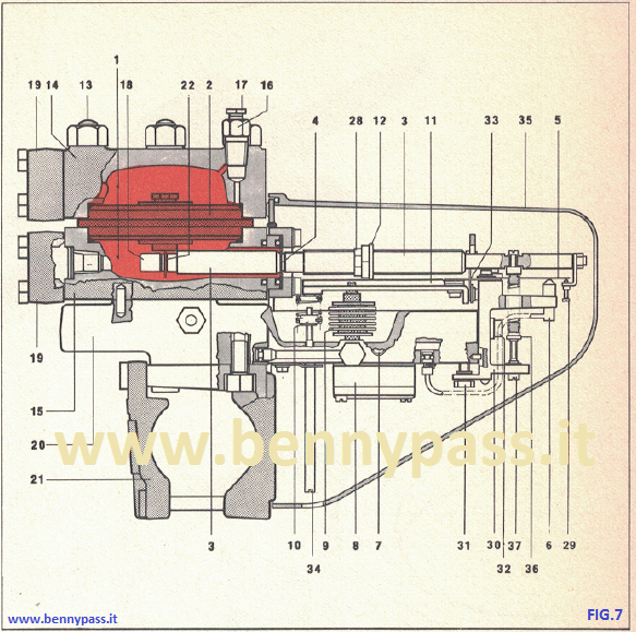 Figure 7 - Measuring Cell with its membrane Figure 7 - Measuring Cell with its membrane
Visual inspection of the Force Lever
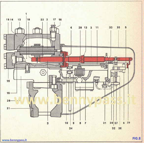 Figure 8 - Force Lever Figure 8 - Force Lever
Leverage of forces
|
 In order to access the force lever, the whole must be disassembled In order to access the force lever, the whole must be disassembled
transmitter, therefore, it is advisable to disassemble this lever only in case of absolute necessity.
The operations that must be performed to disassemble the force lever are as follows (on side of this table).
|
 Perform all the exposed operations for the visual examination of the measuring cell. Perform all the exposed operations for the visual examination of the measuring cell.
Svitare la vite (53) che fissa la molla strozzatura di soppressione dello zero (36) alla leva delle forze (3).
Unscrew the screws (41), securing the reaction bellows (9) to the auxiliary lever (11).
Unscrew the screw (43) that fixes the retaining plate (42) to the control screw (34) of the zero adjustment spring (10).
Turn In a clockwise direction the control screw (34) of the spring of adjustment zero completely until it is free from the spring (10).
Remove the corner plate (44) from the cross-handle fulcrum from the auxiliary lever (11) after having removed the screws (45) that fix it to the nozzle holder slide (30) and to the cross-shaped fulcrum of the auxiliary lever (11).
Unscrew the screws (46) that fix the plate (5) of the modulator assembly and the cross fulcrum on the auxiliary lever (11) to the nozzle holder slide(30).
Remove the four screws (47) securing the flange (24) to the lower body (15) of the measuring cell.
Release the force lever, withdrawing from the measuring cell.
With these operations, the auxiliary lever (11) has been freed: in this way it is possible to access the locking screws (47) of the fixing flange (24) of the force lever (3) to the lower body (15) of the measuring cell.
With these operations the whole transmitter has been virtually disassembled, therefore, it is possible to examine the remaining parts, before reassembling the force lever.
To assemble the force lever, you must proceed in the reverse of the instruction for disassembly.
|
3. Leverage of forces.
5. Lamina modulator group.
6. Modulator group nozzle.
7. bottleneck.
8. Amplifier relay.
9. Reaction bellows.
10. Zero adjustment spring.
11. Auxiliary lever.
15. Lower body of the measuring cell.
20. Transmitter base.
24. force lever fixing flange.
25. Teflon ring gasket.
26. Thrust bridle.
30. Nozzle holder slide.
34. Control screw of the zero adjustment spring.
36. Zero-elimination spring.
37. Suppression spring adjustment screw (36).
41. Fastening screws of the reaction bellows (9) to the auxiliary lever (11).
42. Retaining plate of the zero adjustment spring control screw (10).
43. Plate fixing screw (42).
44. Cross-shaped pivot door at the cross of the auxiliary lever (11).
45. Plate fastening screws (44).
46. Fixing screws of the plate (5) and of the cross fulcrum of the auxiliary lever.
47. Fixing screws for the flange (24) and for fixing the force lever (3) to the lower body (45) of the measuring cell.
48. Connect the plug-in nozzle.
49. Nozzle connection locking plate (48).
50. Plate fixing screw (49).
51. Nozzle supply tube.
52. Fixing screws of the amplifier relay.
53. Fixing screws of the suppression spring to the force lever.
54. Suppression spring fixing pin (36) to the nozzle holder slide (30).
55. Guide screws zero suppression spring.
|
Figure 9 shows the Bellows.
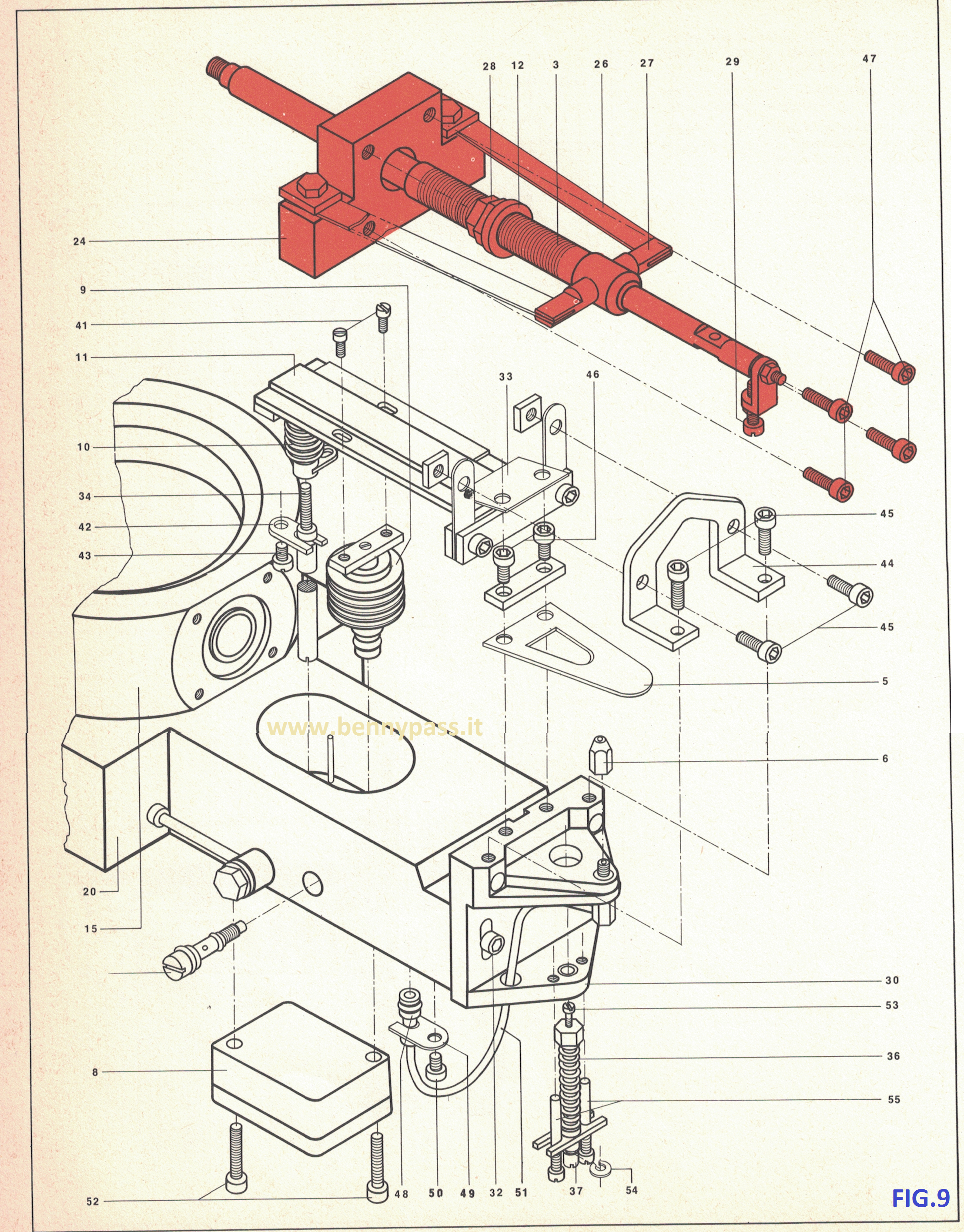
Figure 9 - BellowsInstallation
Visual inspection of the measuring cell
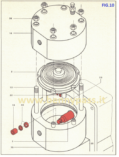 Figure 10 - Diaphragm Figure 10 - Diaphragm
Components:
- 2. Membrane
- 3. Leverage of forces
- 13. Prisoners
- 14. Upper body of the cell
- 15. Lower body of the cell
- 18. Nut that locks the fastening plate (22) of the diaphragm (2) to the lever of forces (3)
- 20. Basement
- 22. Diaphragm fixing plate (2) to the force lever (3)
- 38. Tightening nuts of the upper body of the measuring cell
- 39. Membrane teflon seal (2)
- 40. Locking washers
The examination of the measuring cell is reduced to checking the efficiency status of the membrane (2); that is, there are no oil leaks due to diaphragm breakage.
It should be noted that permanent membrane deformations are found only by testing the linearity of the transmitter outlet pressure.
Sometimes it is necessary to remove the measuring cell to clean it from any more stations due to the sedimentation of the process fluid.
Procedure to remove the membrane
- Insert a 1/4 "Allen key into the pressure inlet port from transmit in the lower body of the measuring cell (15), and loosen the lock nut (18).
- Remove the nuts (38).
- Remove the upper body (14) of the measuring cell from its studs (13).
- Mark the diaphragm and the lower body (15) with a notch measuring cell so it can be put back in the same position during the assembly phase.
- Remove the membrane from the lower body housing.
- Generally, the membrane and the lower body are marked by the manufacturer with a stamp.
Recommendations to reassemble the membrane
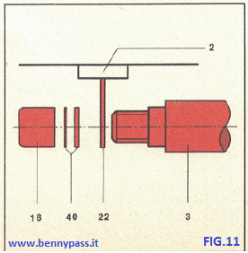 Figure 11 - Diaphragm Figure 11 - Diaphragm
 The two Teflon seals (39) must be intact. The two Teflon seals (39) must be intact.
If the diaphragm is new, it must be marked on its housing position in the lower body of the measuring cell.
Make sure that the two lock washers (40), the plate (22) and the force lever (3) are in the position shown in figure 11 on the side.
The lock nut (18) must be tightened after making sure that the lever (3) of the forces is perfectly horizontal.
Components
- 3. Leverage of forces
- 18. Plate lock nut (22) at the lever (3)
- 22. Plate for fixing the diaphragm to the lever (3)
- 40. Locking washers
Examination
Figure 6 - Modulator group
Components:
- Modulator group
- ReIé amplifier
- Reaction group
- Zero adjustment spring
- Zero suppression spring
| Modulator group |
The nozzle (6), the lamina (5) and the restriction (7) must be kept perfectly clean. |
In order to clean the nozzle and the lamina, proceed in the following way:
Loosen the screw (50) of the plate (49) connection and (48) of the nozzle. Move the plate itself to free the connection
Unscrew the nozzle (6).
Remove the nozzle supply tube (51) from the nozzle holder slide (30), pulling it down.
Thoroughly clean the foil with cotton dampened with alcohol or another suitable solvent. Taking care not to bend it.
Clean the nozzle by inserting a wire of copper or brass, with a diameter maximum of 1 mm.
After immersing it in a solvent, blow it with clean compressed air in order to dry it.
Reassemble it on its slide (30).
Insert the nozzle connection (43) into its housing, being careful not to damage the seal.
Reposition the plate (49) and secure it with the special screw (50).
|
The bottleneck must be kept clean. |
The bottleneck can be examined and cleaned as follows:
Unscrew the restriction (7) and clean it by inserting a wire with a maximum diameter of 0.15 mm.
Lubricate the ring gaskets with vaseline, and reassemble the restriction.
|
| Amplifier relay |
The amplifier relay (8) can be removed from the transmitter after removing the screws (52). |
For the disassembly of the parts that compose it, for their cleaning, see test 4.
|
| Reaction group |
To access the reaction group, consisting of the auxiliary lever (11) and the reaction bellows (9), the operations of the force lever must be performed (see manual force lever) |
Remember that, once the auxiliary lever has been removed, the reaction bellows can be removed from the transmission by taking it with one hand at the base, and pulling it upwards; in fact, it is inserted into a graft. |
| Zero adjustment spring |
The zero adjustment spring (10) is accessible after removing the auxiliary lever, as shown in previous examinations. |
|
| Zero suppression spring |
The zero suppression spring (36) can be released from the lever of the forces (3) by unscrewing the screw (53). |
To disassemble the zero suppression spring (36), proceed In the following way:
Unscrew the screw (53) that secures the spring to the force lever (3).
Remove the split pin (54).
Remove the guide screws (55).
Remove the large part by pulling it out from the front.
|
See Figure 12 below
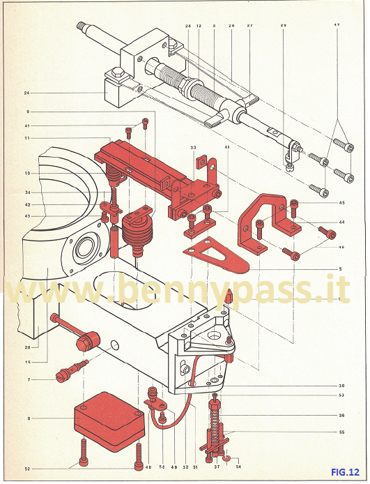 Figure 12 - Assembly Figure 12 - Assembly
Failures and remedies
| Fault |
Cause |
Remedy |
| The output pressure from the transmitter (Pe) is constantly zero despite that a variation of the differential pressure is ascertained. |
- Leakage in the nozzle supply tube (6).
- Amplifier relay (8) dirty.
- Damage membrane (2) of the measuring cell.
- The lamina (5) of the modulator group does not arrive at a useful distance in front of it at the nozzle (6).
- The supply of the transmitter is low.
|
Check and replace it if necessary.
Remove it and clean it carefully.
Replace the membrane.
Check the position of the membrane in the measuring cell and its binding with the lever of forces (3).
Check the tightness of the chamber (+) of the measuring cell.
Check the air supply circuit.
|
| The output pressure of the transmitter (Pu) is inconstant or tends to oscillate. |
- Amplifier relay (8) dirty.
-
The incoming differential pressure is particularly inconsistent.
-
Formations of pockets of gas in the differential pressure adduction piping (in case the process fluid is a liquid).
-
Formations of liquid bubbles on the membrane (in the case that the fluid of the process is a gas).
|
Open the relay and clean it.
Damping the differential pressure variations with suitable devices.
Vent the inlet pipes, and if necessary change the differential pressure system.
Purge the measuring cell.
Install condensate collection barrels if necessary.
|
| The output pressure of the transmitter (Pu) is constantly maximum, although the variation of the differential pressure is ascertained. |
- Amplifier relay (8) dirty.
- Nozzle (6) of the clogged modulator unit.
- The reaction bellows (9) have a leak.
|
Remove it and clean it carefully.
Disassemble and clean it.
Check its seal and replace it if necessary.
|
| The transmitter is calibrated frequently. |
- The transmitter is subject to excessive vibration.
- Efforts imposed on the body of the transmitter by the pressure supply pipes differential supply and output
- Perforated membrane due to the high corrosivity of the fluid.
|
Change the place of installation.
Check and possibly change the path of the pipes.
Replace the membrane with a more appropriate material.
|
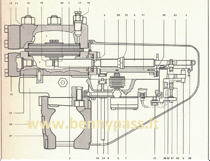 Figure 2 - Construction details Figure 2 - Construction details
1. Measurement cell
2. Membrane
3. Leverage of forces
4. Fulcrum of the force lever (3)
5. Lamina modulator group
6. Modulator group nozzle
7. Throttling
8. Amplifier relay
9. Reaction bellows
10. Zero adjustment spring
11. Auxiliary lever
12. Transmission field adjustment slider
13. Prisoners of the measuring cell
14. Upper body of the measuring cell
15. Lower body of the measuring cell
16. Vent valve
17. Vent valve
18. Plate locking nut (22) to the force lever (3)
19. Connection flsngette
20. Transmitter base
21. Anchor bracket
22. Diaphragm fixing plate (2) to the force lever (3) |
14. Upper body of the measuring cell
15. Lower body of the measuring cell
16. Vent valve
17. Vent valve
18. Plate locking nut (22) to the force lever (3)
19. Connection flsngette
20. Transmitter base
21. Anchor bracket
22. Diaphragm fixing plate (2) to the force lever (3)
28. Control slider locknut (12) of the transmission range
29. Micrometric screw for adjusting the position of the plate (5)
30. Nozzle holder slide (5)
31. Nozzle holder slide screw (30)
32. Nozzle holder fixing screw (30)
33. Fulcrum of the auxiliary lever (li)
34. Zero adjustment spring control screw
35. Lid
36. Zero suppression spring
37. Zero suppression spring control screw (36)
|
Special applications
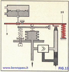 Figure 13 - Special applications Figure 13 - Special applications
Zero suppression
Differential to be transmitted, so the so-called suppression is necessary of zero. This suppression consists in applying a spring (36), used in compression, at the free end of the force lever (3). In this way, the lever acts as a fixed force due to the suppression spring. Therefore, the force due to the differential pressure will succeed in moving the lever only after overcoming the suppression spring's resistance. The outlet pressure will assume a value of 3 psi when the pressure differential has assumed a value equal to the minimum fixed, using the deletion.
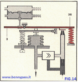 Figure 14 - Special applications Figure 14 - Special applications
Inversion action
In case you want to have the maximum outlet pressure (15 psi) when the differential pressure is zero and the inversion of the action is carried out. This version can be made by sending the P1 in the chamber and P2 in the + chamber and applying it to the free end of the force lever (3), a spring (36) used in traction. This spring should be calibrated when the differential pressure output is cancelled, assuming the value of 15 psi.

|


