
|
Ring Main System Busbar - working principle
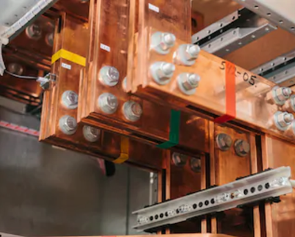
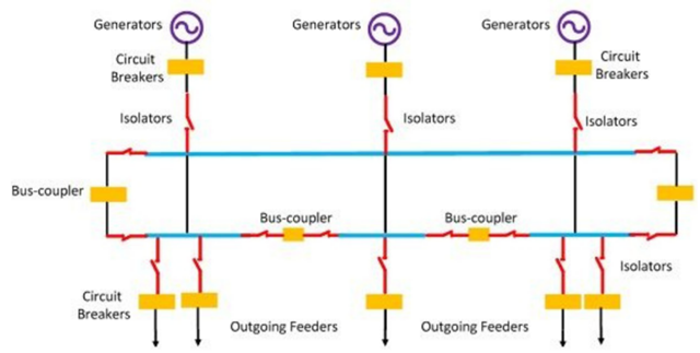
A Ring Main System (RMS) busbar operates by forming a closed-loop (ring) configuration, where electricity flows from the source in two directions to feed multiple distribution nodes. Each load connects to the ring via a Ring Main Unit (RMU) containing switches, allowing any node to receive power from either side if a section fails, ensuring high reliability and continuous supply Key Working Principles
This system is commonly used in medium-voltage (MV) distribution, especially in urban areas or industrial sites where supply reliability is paramount Working Principle The core principle is bidirectional power flow, allowing electricity to reach any load point from two different directions.
For more details see Figure below
Key Components & Functions
Summary of Benefits
|
|
Single Busbar working principle
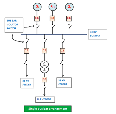
A single busbar system is the simplest substation arrangement, featuring a single, continuously energized conductor (bus) to which all incoming power sources and outgoing feeders are directly connected via circuit breakers and isolators. It operates as a central, low-cost hub for distributing electricity, but any bus fault or maintenance causes a total,100% shutdown. Working Principles
For more details see Figure below
Key Features
Key Characteristics
Advanced Variation: Sectionalized Single Busbar To improve reliability, the single bus can be "sectionalized" using a bus tie (circuit breaker and isolators). This allows a faulty section to be isolated so that the rest of the bus can continue providing power.
|
|||||||||||||||
|
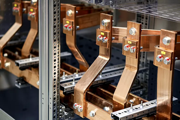
Construction and Design Criteria of MCC BusBars
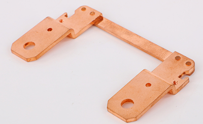
A bus bar is a thick, conductive metal strip (copper or aluminum) that acts as a central, low-impedance node to collect, conduct, and distribute high-amperage electricity from incoming sources to multiple outgoing loads. It operates on the principle of passive conduction, ensuring a consistent, high-capacity, and orderly distribution of power with minimal voltage drop Key Working Principles
Types of BusBar Systems
Applications Busbars are essential components in:
Types of Busbars Suppliers have developed a wide variety of busbar types to meet the needs of a growing number of applications. Busbars can be grouped by the following characteristics:
The shape of busbars impacts their conductivity due to skin effect and the heat transfer from the bar. In most cases, the goal is to have a high ratio of surface area to cross-sectional area. Here is a list of the most common shapes:
A single-phase busbar has two circuits: one that is live and another that is neutral. Three-phase busbars use four conductors, one for each phase and another as a neutral run. Where single- and three-phase types deal with alternating current (AC) applications, some busbars carry direct current (DC). The Advantages of Busbars Engineers choose busbars for many reasons, usually due to cost, performance, and safety. In most cases, the following characteristics drive the choice of busbars over other power distribution options:
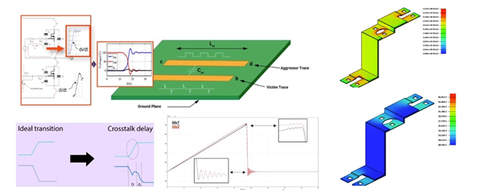
Simulation-driven Busbar Design As can be seen by the different types of busbars, engineers have lots of choices in material, configuration, coatings, and geometry. Multiphysics simulation tools are a perfect complement to the design process because they provide a fast and accurate way to understand the interaction of electromagnetic fields, heat generation, heat transfer, and structural response. Engineers want to optimize their busbar designs to have maximum efficiency, operate safely, and minimize cost. Once they understand what the routing of the circuit is, they can create a low-frequency
|
Electrical
|
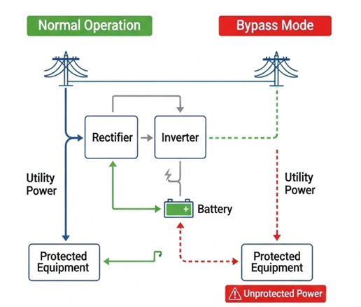
UPS Static Bypass Switch - Working Principle
A UPS static bypass switch is an automatic, solid-state device (usually thyristors) in online UPS systems that instantly transfers the critical load to utility power (<4ms to 20ms) if an internal fault, inverter failure, or overload occurs. It ensures continuous, no-break power without interruption, acting as a "safe failure to mains" mechanism. Key Aspects of the Working Principle
Static Bypass vs. Maintenance Bypass
Working Principle The switch typically utilizes Silicon Controlled Rectifiers (SCRs) or thyristors arranged in inverse parallel. Because these are solid-state components with no moving parts, they can transfer the load in less than 4 milliseconds (approx. 1/4 of an electrical cycle), which is fast enough for most sensitive IT equipment to continue operating without rebooting.
Key Functions
Note: While in bypass mode, your equipment is no longer protected from power surges, sags, or frequency fluctuations, as it is receiving raw utility power directly. |
|
UPS - Backfeed Protection - Working Principle UPS backfeed protection prevents dangerous voltage from travelling from the UPS output back to the input terminals during a mains power failure. It works by detecting reverse current, often due to a faulty static switch, and triggering a contactor or relay to physically isolate the input, ensuring safety for personnel working on the upstream supply. Key Working Principles
This system is crucial to avoid "back-feeding," which could otherwise keep the input terminals live even when the main utility power has been cut off. UPS backfeed protection is a safety mechanism designed to prevent hazardous voltage from flowing backward from the UPS output toward the input terminals when the main utility power has failed. This protection is essential to safeguard service personnel working upstream from electric shocks and to prevent damage to connected electrical infrastructure. Working Principle The core principle is to electrically isolate the UPS from the input grid the moment a power failure or fault is detected.
Implementation Methods According to international standards like BS EN 62040-1:2019, backfeed protection can be implemented in two ways:
Why It Matters
|

+(39) 347 051 5328
Italy - Kazakhstan


09.00am to 18.00pm
About
We offer the best and economical solutions, backed by 27+ years of experience and international standards knowledge, echnological changes, and industrial systems.
Our Services
Marketing Materials


Marketing Materials1


