
|
Type 1 or Type 2 SPD upstream of the UPS - Working Principle
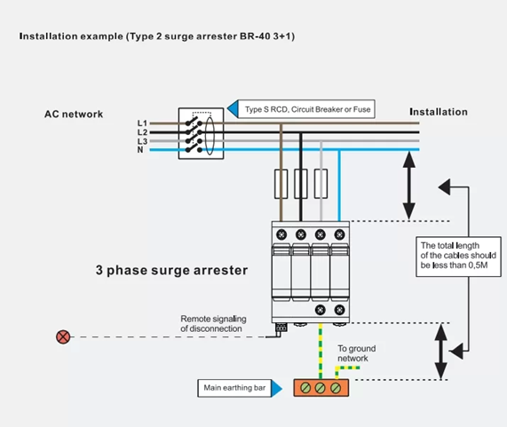
Type 1 or Type 2 Surge Protective Devices (SPDs) installed upstream of a UPS protect it from external (lightning) or internal (switching) high-voltage spikes, crucial for sensitive, expensive equipment. Type 1 handles direct strikes at the service entrance, while Type 2 handles downstream switching surges, ensuring clean, stable power reaches the UPS. Working Principle & Setup
Key Considerations
Using both, or a combined Type 1+2, provides the most comprehensive protection for the UPS and connected downstream equipment. In a power system with a UPS, Type 1 and Type 2 Surge Protection Devices (SPDs) act as the primary defense layers for the UPS itself and its downstream loads. A cascaded approach is essential because a UPS's internal surge protection is typically limited and cannot withstand high-energy surges. Working Principle SPDs are high-impedance devices connected in parallel with the power lines. When a voltage surge exceeds a specific threshold, the SPD’s internal resistance drops instantly (within nanoseconds), creating a low-impedance path to divert excess current safely to the ground.
Coordination Upstream of the UPS Installing these devices upstream of a UPS provides specific technical benefits:
|
|
UPS prolongs battery life - Working Principle Proposing, charging, and operating lithium-based batteries between 20–80% capacity while keeping temperatures cool (20–25°C) maximizes lifespan by minimizing chemical degradation, voltage stress, and thermal expansion.This method slows down capacity loss by reducing cycle intensity and preventing the formation of lithium plating. Working Principles of Extended Battery Life
Key Tips to Prolong Life
Prolonging battery life involves managing the chemical and physical processes that occur during the movement of ions between electrodes. By minimizing internal stress, you can delay the natural degradation of the battery's components.
A battery stores energy as chemical potential and converts it into electrical energy through an electrochemical reaction.
Batteries don't last forever because each cycle causes microscopic damage:
o extend lifespan, you must minimize the stress caused by these reactions:
|
|
UPS square Wave - Working Principle
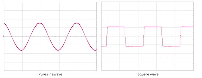
A square wave UPS converts DC battery power to AC power by abruptly switching polarity, creating a, rough, block-shaped wave rather than a smooth sine wave. Utilizing an H-bridge circuit, it switches MOSFETs or IGBTs on and off to generate alternating positive and negative voltage pulses, ideal for simple, non-sensitive equipment at a low cost. Key Working Principles
Characteristics
A square wave UPS (Uninterruptible Power Supply) operates by converting DC battery power into a basic, non-sinusoidal AC output characterized by sudden transitions between maximum positive and negative voltages. Working Principle The core mechanism is a process of electronic switching, typically utilizing an H-Bridge circuit:
Key Characteristics & Limitations
|
|
UPS Modified/Simulated Sine Wave - Working Principle
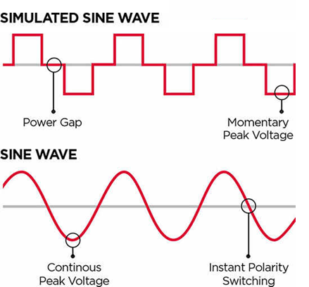
A UPS with a modified or simulated sine wave (also known as a quasi-sine wave) works by converting battery DC power into AC using a stepped, non-smooth wave that approximates a sine wave rather than a smooth, continuous curve. This process produces a choppy, square-like waveform with abrupt, abrupt rises and falls in voltage. It is a cost-effective alternative suitable for basic electronics but can cause motors to run hot and cause buzzing in some devices. Key Aspects of Modified/Simulated Sine Wave UPS
Difference from Pure Sine Wave While a pure sine wave is a smooth, consistent wave matching the grid, a modified sine wave is a "choppier," less stable, and less smooth version. It acts like a "rough draft" of a sine wave. A Modified Sine Wave (also called a Simulated Sine Wave or Quasi-Sine Wave) is a stepped, staircase-like approximation of a pure AC waveform. It is a cost-effective design primarily found in standby and line-interactive UPS systems. Working Principle The core goal is to convert DC (Direct Current) from the UPS battery into AC (Alternating Current) for your devices. Here is how it achieves this:
Why use it?
Critical Limitations
|
|
UPS Float Mode (Maintenance): - Working Principle UPS Float Mode is a maintenance operating state where the charger keeps batteries fully charged (typically 2.25V–2.30V per cell) during standby. It works by supplying a low-level, constant voltage to compensate for self-discharge, ensuring immediate availability, preventing overcharging, and extending battery life Working Principle & Details
Key Benefits of Float Mode
Important Maintenance Note: While floating is good for standby, Oreate AI suggests regular discharge cycles (e.g., every 3-4 months) to prevent "memory effect" and verify capacity. UPS Float Mode (also known as Maintenance Mode) is a charging state designed to keep batteries at 100% capacity while the UPS is in standby. It prevents the natural self-discharge of batteries without the risks of overcharging or "boiling" the electrolyte. Working Principle The working principle centers on constant voltage regulation.
Key Functions
Maintenance Best Practices While Float Mode is safe for long-term use, it can cause "passivation" (a type of battery memory) if left indefinitely. IEEE 1188 standards recommend:
|

+(39) 347 051 5328
Italy - Kazakhstan


09.00am to 18.00pm
About
We offer the best and economical solutions, backed by 27+ years of experience and international standards knowledge, echnological changes, and industrial systems.
Our Services
Marketing Materials


Marketing Materials1


