
|
Solid earthing (or grounding) Working Principle
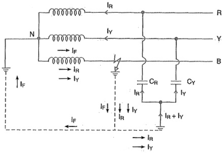
Solid earthing (or grounding) works by directly connecting the neutral point of a generator or transformer to the earth using a conductor with negligible resistance and reactance. This creates a low-impedance path that keeps the neutral at earth potential, prevents transient overvoltages, and allows for rapid, high-magnitude fault current detection, which ensures swift protection device operation. Key Working Principles and Characteristics
Applications
The operating principle of solid (or "effective") earthing consists of directly connecting the neutral point of a three-phase system (such as a transformer or generator) to earth via a conductor with negligible impedance. How It Works
Advantages and Disadvantages
Common Applications
Conclusion The solid grounding of neutral point has the following advantages:
ApplicationsSolid grounding is usually employed where the circuit impedance is sufficiently high so as to keep the earth fault current within safe limits. This system of grounding is used for voltages upto 33 kV with total power capacity not exceeding 5000 kVA. Calculation Low-reactance Grounding ased on network constant ratios, the criteria to qualify as reactance grounded is: Xₒ/X1 > 3 as seen at fault, but less than the value necessary for resonant grounding. Inserting a low-reactance such that Xₒ/X1 ≤ 3 at fault, is not reactance grounding. Xₒ/X1 > 3 and the system is deemed reactance grounded. Recommendations It is not proper to endanger a generator winding with fault currents higher than the three-phase current at the terminals. In generators, the ground-fault currents are higher than the three-phase fault currents because the internal impedance seen by the ground-fault is less than the impedance to three-phase faults. The high current produces excessive heating and mechanical forces. A suitable current limiting impedance, like a low-reactance reactor, should be installed in the neutral to avoid generator damage. In transmission and distribution systems, without directly connected rotating machines, the neutrals of the transformers are usually effectively grounded and reactors are not typical. The phase-to-ground fault current should range from 25% to 100% of the three-phase fault current. Less than 25% may cause damaging transient overvoltages. Choose the value of reactance needed to limit the ground-fault current to the preferred amount. The ratio is
Limiting the ground-fault current to 60% of the three-phase fault current is the borderline between effective grounding and reactance grounding. Low-resistance Grounding In the USA, low-resistance grounding is the most popular method utilized to limit ground-fault current. The value of resistance is much lower than the high-resistance method and ranges from 5% to 20% of the three-phase fault current. Some applications limit the ground current to around 50A to 600A. |
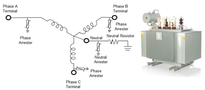
Medium voltage transformer with star point connection to earth
Medium voltage (MV) transformers with a star (Y) connected winding, particularly on the secondary side, often have the neutral point grounded to ensure system stability, safety, and proper fault protection. This configuration allows for phase-to-neutral loading, reduces transient overvoltages, and limits fault currents to safe levels, often utilizing a Neutral Grounding Resistor (NGR). Key Aspects of Star Point Grounding in MV Transformers
In some cases where the main transformer is delta-connected, a separate grounding transformer (e.g., a Zigzag transformer) is used to create a star point for grounding purposes. In medium voltage (MV) systems (typically 1–35 kV), a transformer with a star point (neutral) connection to earth serves as a critical safety and stability mechanism. While the low-voltage (LV) side is almost always solidly grounded, MV grounding methods vary based on the desired fault current control. Common Grounding Configurations
Key Technical Benefits
Use of Earthing Transformers If the main MV winding is Delta-connected (which has no natural star point), an Earthing Transformer (Zig-zag or Star-Delta) is used to create an artificial neutral for grounding purposes.
|
|
Active/Automatic Load Sharing
Active/Automatic Load Sharing systems automatically redistribute electrical loads across multiple transformers or power sources based on real-time demand, typically using PLCs, microcontrollers, or relays to manage parallel operations. This technique protects equipment from overheating and failure by connecting secondary ("slave") units when the main transformer exceeds capacity, improving efficiency, reducing voltage drops, and increasing reliability in industrial or distribution networks. Key components of automatic load sharing systems often include:
Key Benefits
Applications
Active load sharing is often implemented to enhance the longevity of distribution transformers and to improve the overall efficiency of energy systems.
Active or automatic load sharing is a dynamic power management technique used to distribute electrical demand across multiple sources—typically transformers—to prevent overloading, enhance system reliability, and optimize efficiency.
How It Works
The system continuously monitors real-time parameters such as current, voltage, and temperature to make automated distribution decisions:
Core Components
Key Benefits for 2026
|
|
Isochronous Control Sharing
Isochronous control sharing enables multiple generators in an islanded, parallel system to maintain constant, stable frequency (e.g., 50/60 Hz) regardless of load changes, preventing system shutdowns. By using communicating electronic governors, units share load proportionally, avoiding the instability of uncontrolled, independent isochronous operation. Key Aspects of Isochronous Load Sharing
While one machine can operate in simple isochronous mode, parallel operation requires coordinated, electronic load sharing to maintain stability. Isochronous load sharing is a control method used in power generation to allow multiple generators to operate in parallel while maintaining a constant system frequency (typically 50 or 60 Hz), regardless of the total load. Key Characteristics
How It Works
Comparison with Droop Control
System Risks Single Point of Failure: Because it relies on constant communication, a break in the load-sharing line can cause units to drift or become unstable. Many systems are designed to automatically revert to droop mode if a communication fault is detected. |
|
Reactive Power (kVAR) Sharing
Reactive power (kVAR) sharing in parallel generators is controlled by adjusting the alternator field excitation (Automatic Voltage Regulator - AVR) to balance reactive load and maintain system voltage. Increasing excitation (over-excitation) makes a generator take more load, while decreasing it (under-excitation) makes it take less, without significantly affecting real power (kW) Key Principles of kVAR Sharing
How to Adjust kVAR Sharing
In modern systems, digital controllers often handle this automatically via CANbus, balancing the kVAR Load based on real-time data.
Reactive power (kVAR) sharing is the proportional division of reactive load between multiple generators or inverters operating in parallel. While active power (kW) is managed by engine fuel input, kVAR sharing is primarily controlled by the alternator field excitation system via an Automatic Voltage Regulator (AVR).
Core Mechanisms of kVAR Sharing
Why Effective Sharing is Critical
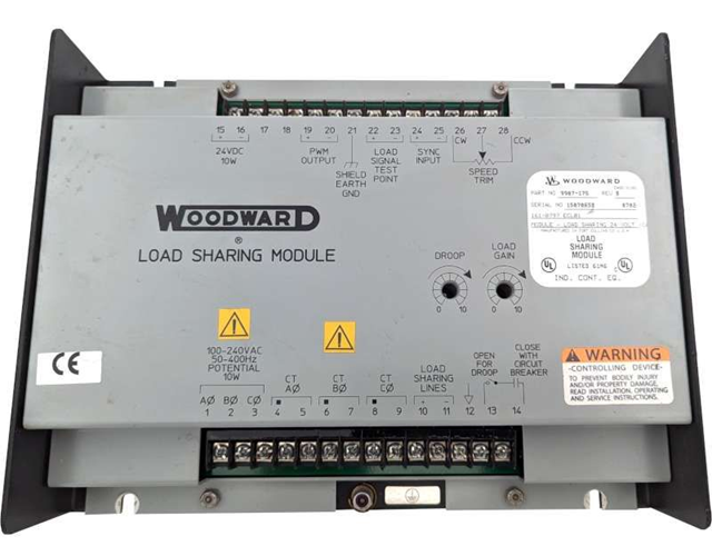
Modern Control Systems In 2026, most multi-generator systems use digital paralleling controllers (e.g., Woodward, ComAp, or DEIF). These systems exchange data via high-speed communication lines (like CANbus) every 50–100 ms to automatically adjust excitation and fuel levels, maintaining error margins within 2%.
|

+(39) 347 051 5328
Italy - Kazakhstan


09.00am to 18.00pm
About
We offer the best and economical solutions, backed by 27+ years of experience and international standards knowledge, echnological changes, and industrial systems.
Our Services
Marketing Materials


Marketing Materials1


