
|
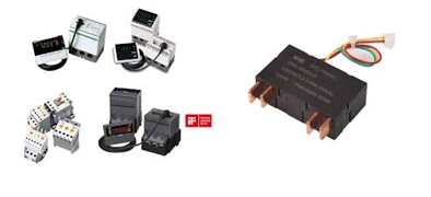
Solid-State/Digital Relays
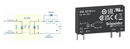
Solid-State Relays (SSRs) work by using a low-power input signal to activate an internal light source (like an LED) which triggers a photosensitive component, isolating the control circuit from the load circuit; this component then acts as a silent, fast-switching semiconductor (like a MOSFET or Triac) to switch high power to the load, offering durability, speed, and no moving parts, unlike traditional mechanical relays. Working Principle Breakdown
Key Features & Types
Solid-State Relays (SSRs) and Digital/Numerical Relays operate on different principles suited to their respective roles in power switching and system protection.
A Solid-State Relay is an electronic switching device that controls a high-power load using a low-power control signal without any moving parts. Its working principle is based on optical or magnetic coupling to achieve electrical isolation.
Digital or Numerical Relays are microprocessor-based devices used for power system protection and monitoring rather than simple on/off switching.
Comparison Summary for 2026
ds |
|
Electromechanical relay
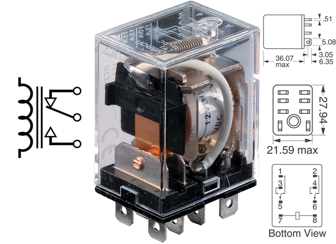
An electromechanical relay operates using an electromagnet to mechanically switch electrical contacts: when a small current energizes the relay's coil, it generates a magnetic field that attracts a movable armature, causing physical contact movement to open or close a separate power circuit. Once the coil is de-energized, a spring returns the armature to its original position, breaking the contact Core Components
Working Principle in Steps
Electromechanical relays (EMRs) operate as electrically controlled mechanical switches, using electromagnetic induction to physically open or close electrical contacts. This mechanism allows a low-power control signal to manage high-power load circuits safely by providing galvanic isolation between the two. Core Components
4-Step Working Sequence
Key Specifications for 2026
Comparison to Alternatives Unlike Solid State Relays (SSRs), which use semiconductors (like MOSFETs) to switch current without moving parts, electromechanical relays are preferred for their complete electrical isolation, ability to handle high inrush currents, and lack of leakage current when open. For highly sensitive or fast-switching applications in 2026, SSRs are often chosen, while EMRs remain the standard for robust, high-voltage industrial protection.
|
|
Motor and generator relays
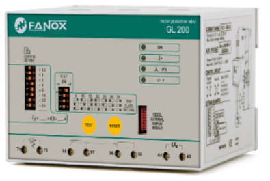
Motor and generator relays work on electromagnetic induction, using a low-power signal to control high-power circuits by creating a magnetic field in a coil that moves an armature, physically opening or closing contacts to switch the connected motor or generator circuit, often for protection (like against faults) or control. The basic principle involves energizing a coil, generating magnetism to pull an armature, changing contact states (like tripping a breaker), and then de-energizing to reset, often with a spring. Working Principle (Electromagnetic Relay) This video provides a detailed animation of how an electromagnetic relay works:
Key Components
You can see the key components of a relay in this diagram: Application in Motors & Generators
Motor and generator relays operate primarily on the principles of electromagnetic induction and current balancing to control or protect high-power machinery using low-power signals.
Relays in motor systems serve two main roles: starting the motor and protecting it during operation.
Generator relays are primarily "protective" and often operate on more complex differential logic to detect internal faults.
|
|
Voltage & Frequency Relays
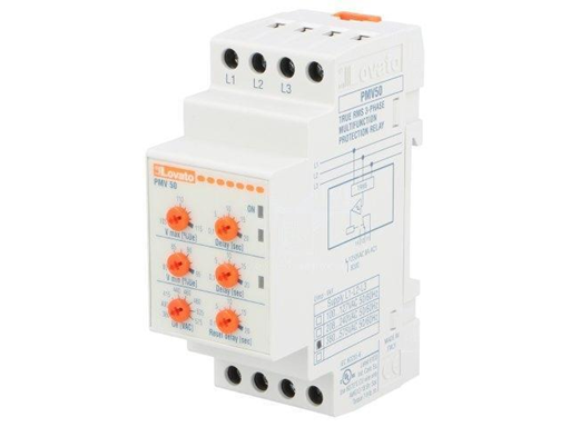
Voltage & Frequency Relays are crucial electrical protection devices that continuously monitor grid voltage and frequency, tripping circuits or triggering alarms when levels go outside safe, preset limits to prevent equipment damage and system collapse, vital for stable operation, especially with distributed generation like solar/wind. They detect over/under voltage/frequency, phase loss, imbalance, and sequence, acting as essential grid interface protection to ensure safety and compliance with utility standards Key Functions & Features
How They Work
Importance
Voltage and frequency relays are protective devices that monitor electrical parameters in a power grid or industrial system to ensure they remain within safe operating limits. They are critical for protecting equipment and maintaining system stability, particularly in systems with in-plant generation or sensitive loads. Core Functions
Key Features & Monitoring Capabilities Modern numerical or microprocessor-based relays, such as the Siemens SIPROTEC or Schneider Electric Easergy, offer advanced monitoring:
Common Applications
Standard ANSI Device Numbers In electrical diagrams, these functions are typically identified by ANSI standard numbers:
|
|
Locked Rotor Relays (or Functions) protect electric motors from damage by detecting when the rotor stops turning (locks) during startup, a dangerous condition where current stays extremely high, potentially melting windings. These relays monitor high starting current, allowing a brief delay for normal startup but tripping the motor if current remains excessive for too long, preventing overheating and catastrophic failure. They are often part of advanced motor protection relays, offering adjustable settings for current and time to match specific motor needs, protecting against issues like jammed impellers or bearing failures This video provides a simple explanation of locked rotor protection: How They Work
You can watch this video to learn more about the locked rotor current: Key Features & Benefits
Common Applications
Examples
A locked rotor relay is a protection device that safeguards electric motors from damage by detecting when the motor's rotor fails to rotate or is otherwise mechanically locked while power is applied. The relay monitors for high current that persists beyond the normal startup period and then disconnects power to prevent overheating and burnout.
Function and Operation When an electric motor starts, it draws a temporary, high "inrush" or locked rotor current, typically several times its normal running current, because there is no back electromotive force (EMF) generated by a spinning rotor to oppose the applied voltage. As the motor accelerates, the back EMF increases, impedance rises, and the current naturally drops to the normal running level. A locked rotor relay accounts for this normal inrush current by incorporating a time delay. If the high current persists beyond this safe time delay (indicating the motor has not started rotating or has stalled), the relay will send a trip signal to the motor contactor or circuit breaker, cutting the power supply and preventing potential damage to the windings and other components.
Locked rotor conditions can be caused by:
Types and Examples Locked rotor protection is often integrated into comprehensive motor protection relays, which may also offer protection against overload, phase loss, current unbalance, and short circuits. Examples of motor protection relays that include this function are:
These modern relays are often microprocessor-based and feature adjustable settings for current thresholds and time delays, allowing for customized protection based on specific motor characteristics and application requirements. |

+(39) 347 051 5328
Italy - Kazakhstan


09.00am to 18.00pm
About
We offer the best and economical solutions, backed by 27+ years of experience and international standards knowledge, echnological changes, and industrial systems.
Our Services
Marketing Materials


Marketing Materials1


