
|
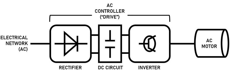
AC Motor Control Basics An AC motor controller is known as a device that controls the speed of the AC motor. An AC controller can also be referred to as a variable frequency drive, adjustable speed drive, frequency converter and more. The AC motor receives power, which the AC motor controller converts into an adjustable frequency. This adjustable output allows the motor speed to be precisely controlled.
Figure 1 -Motor control speed Diagram
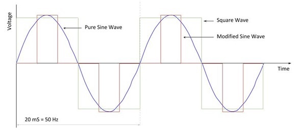
What are AC Motor Controllers? The operation of AC motors is explained thoroughly in our article on induction motors and is a good review on how AC motors convert electromagnetism into useful mechanical energy. How do AC Motor Controllers work? As previously stated, AC controllers convert an input AC frequency into a DC current that simulates an AC frequency, which can then be set by the user, thus controlling the speed of the motor. This is accomplished using three main components: a rectifier, an inverter, and a DC circuit that connects the two. There are also methods for increasing the slip of an AC motor, which will change the speed of rotation in relation to the AC frequency, thus controlling speed. Increasing the slip can be done by either varying the resistance through the motor coils (variable series resistance, see our article wound rotor motors), or varying the voltage to the coils (variable voltage transformers); however, AC drives are more commonplace, as they are more modular and have been engineered to give the user precise digital control over their motor without using integrated components such as resistors or rheostats in the motor windings. Types of AC motor controllers There are some common ways in which AC drives take incoming AC current and transform it into a simulated, controllable frequency. In each method, the goal is to allow operators to input frequency commands to the stator RMF, and as such change the rotation speed of the rotor. There are three main methods for doing this: variable voltage inversion (VVI), pulse-width-modulation (PWM), and flux vector drives. Variable Voltage Inversion In this method, the AC frequency of the power source is rectified to a DC current, which is then increased and decreased in discrete steps to imitate a sine wave (or how a true AC current oscillates). This way, operators can regulate these steps to effectively change the motor speed, and these are commonly referred to as six-step inverters (though different steps exist). Figure 2 below shows an example of how a VVI controller sends stepwise power to a motor, simulating a true sine wave:
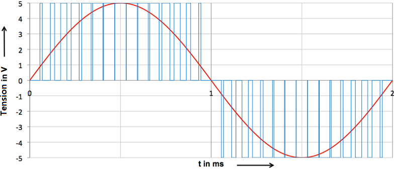
Figure 2 - Voltage over time graph representing how VVIs allow speed control in AC motors Note: Notice that, if more steps were added, it would give a better approximation to the true sine wave. Pulse-Width-Modulation Pulse width modulator circuits, or PWMs, are a popular method to simulate AC oscillations, as they often provide more precise control than variable voltage inverters. They do so by rapidly switching the current (or “pulsing” it) to match the area under the curve of the true sine wave. Recall from calculus that the integrals of any two continuous graphs are equal if their areas under their curves are equal; the goal of PWM is to more accurately approximate the area of a sine wave using many pulses of voltage, and the density of these pulses will dictate the size of the simulated sine wave (and thus change the motor speed). Figure 3 visualizes these spikes on a voltage over time graph:
Figure 3 - PWM graph compared to a true sine wave Note: Notice how the pulses change frequency as they move along the sine wave, but do so in an orderly, equidistant fashion. Vector flux Flux vector drives not only vary the frequency of the current to change the speed of the motor but can also change the motor’s torque as well. They can do this by taking advantage of the motor’s magnetic flux (the number of magnetic field lines passing through a surface, in this case, the coils) as a portion of the current in all induction motors must generate the magnetic coupling between the rotor and stator. The remaining current is the portion that generates torque, and flux vector drives hold the coupling current to a minimum while allowing operators to adjust this torque-producing current. This is easier said than done, as controlling both torque and flux current is analytically intensive, and requires continuous transformations between coordinate systems. Flux vector drives, therefore, require microprocessor-based controllers, software, and oftentimes encoded sensors to precisely tune the independent currents. These drives typically provide speed accuracy of up to 0.3%, and while more impressive than the other two options, comes at a heavier installation and operational cost. Applications and Selection Criteria AC motor controllers have upgraded traditional AC motors, and have allowed them to serve functions in even more areas of industry. One of the most common areas where AC drives are implemented is in HVAC systems, specifically in fans, pumps, and blowers. Designers can optimize the airflow through a building by electrically signaling these components to quickly increase or decrease their speeds, conditioning the building with more efficiency, and saving the owner money on such costs. They also save manufacturers from excess wear and tear on their motors, as AC drives regulate the inrush of starting current, which can damage the motor over repeated cycles of successive starting and stopping. They pair well with integrated motor systems, and anyone looking to control many motors at once should seriously consider AC motor controllers.
Taking some time to seriously consider these questions will not only help you to find a better suited AC drive but also to optimize its performance at a reasonable cost. |
|
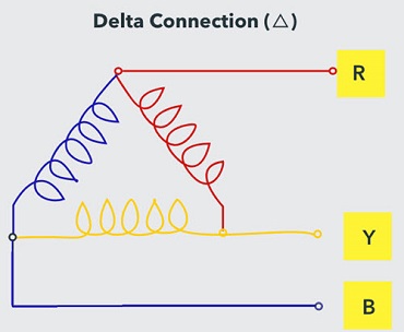
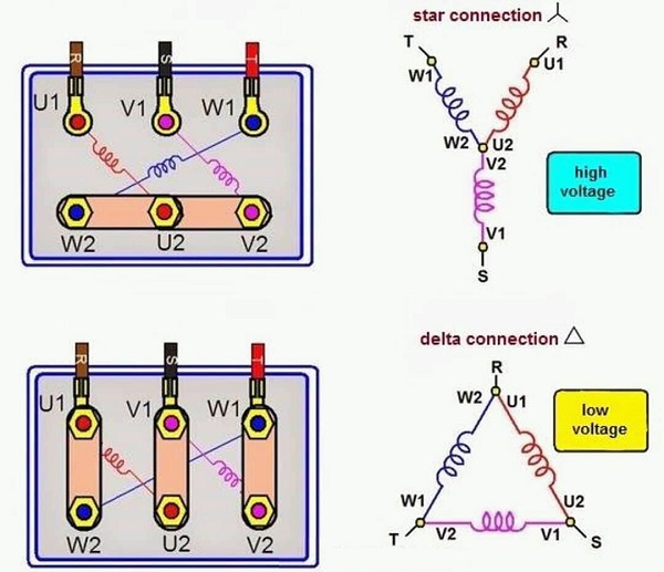
STAR – DELTA Connection
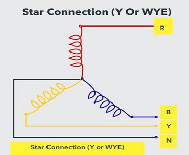
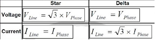
Difference Between Star And Delta Connections
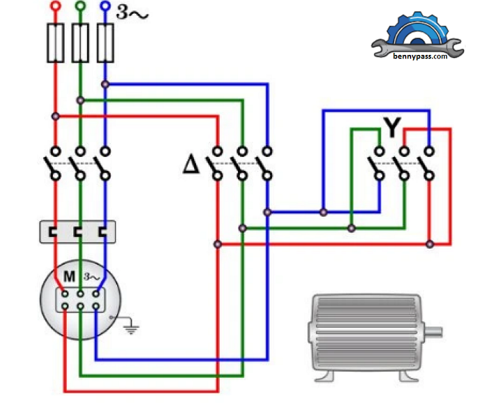
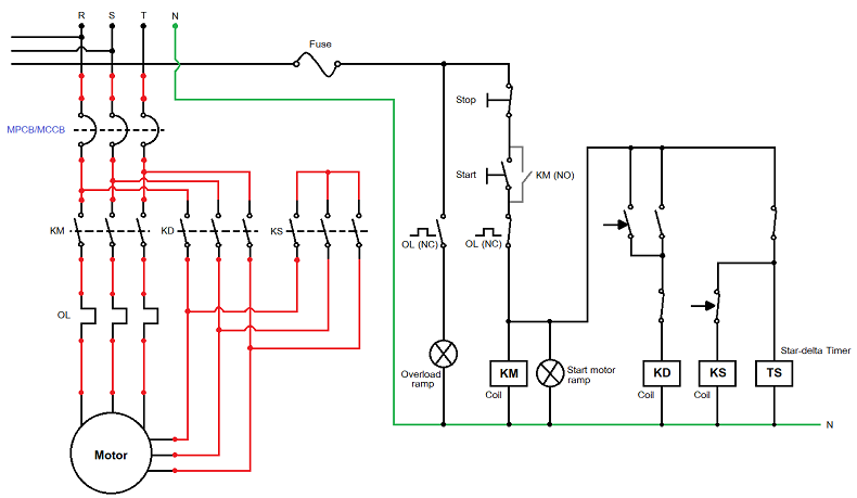
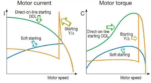
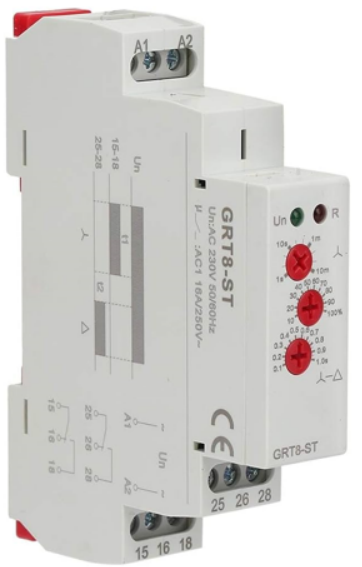
STAR – DELTA Starter The Star Delta starter is the most basic starting method for minimizing the inrush starting current of an induction motor. For typical operation, the starter can be utilized with all squirrel-cage induction motors that are delta connected. The decrease of the high motor current reduces the motor’s starting torque. Star-delta starting is thus particularly ideal for drives that are not loaded until after starting. The starting time is longer than with direct starting, which is noticeable when driving higher inertial loads. For more details see Figure 3 below
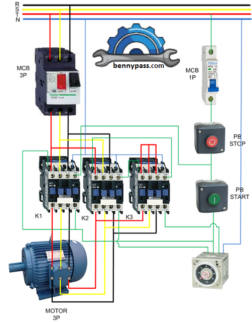
Figure 3 - Star-Delta Connection including devices To limit starting current, a reduced voltage starter is required to start a large motor. The star delta starter is a lower voltage starter that applies 1/√3 voltage during the starting process. Star Delta Starter Components The following are the primary components of a wye-delta starter:
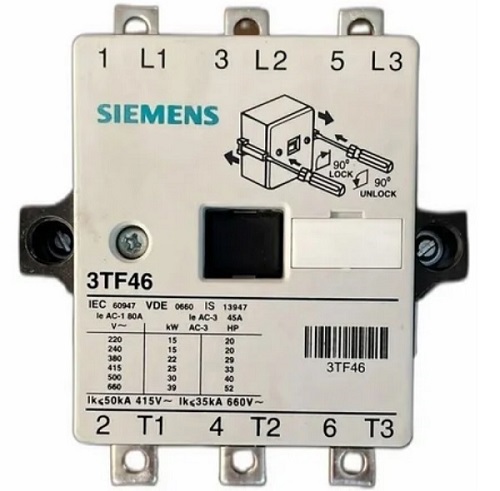
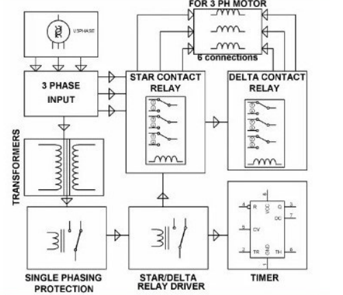
Figure 4 - Components Installation Contactors A contactor is a high-current-rated heavy-duty relay used to power the induction motor. Contactors have current ratings ranging from 10A to several hundred amps.
The main contactor & delta contactor are AC3 type and rated at 58% of the motor’s current rating. During the operation of the induction motor, these contactors are closed.
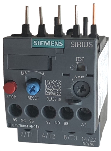
Figure 5 - Contactor A star contactor, on the other side, only carries star current when the motor is turned on. Because the starting current is 1/3 the rated current, the star contactor can be of the AC3 type and 33% of the full load current rating. Because these contactors only control winding current, which is 33% of the full load current in the star delta starter, the three contractors used in the star delta starter are smaller than the single contactor used in the DOL starter. Overload Relay As with induction motors, the majority of winding failures are caused by overloading, operating on an unbalanced voltage supply, and single phasing owing to phase loss, which can lead to excessive heating and motor winding insulation degradation.
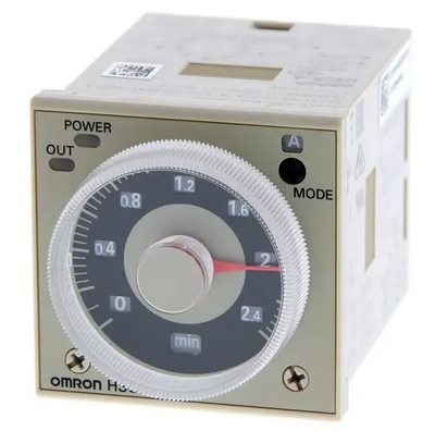
Figure 6 - Overload Relay To prevent windings against overloading and short-circuiting in the internal winding, overload protection is required. As a result, the 3-pole thermal overload relay prevents all of these circumstances. Timer The timer in the wye-delta starter’s fundamental function is to switch the contactor from star to delta when the motor reaches almost 80% of full load speed.
Figure 7 - Omron Timer
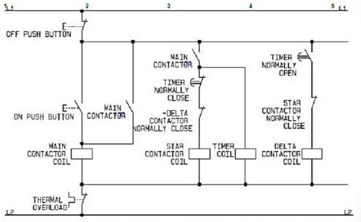
The fuse unit Three fuses are connected in series with the motor circuit to protect it against external overcurrent and short circuit faults. In addition, one fuse is used to protect the wye-delta starter’s control circuit. MCB A circuit breaker is an electrical switch that operates automatically to protect an electrical circuit from harm caused by excess current from an overload/short circuit. Its primary function is to interrupt current flow when a problem is identified. In addition a fuse, which can only be used once before needing to be replaced, a circuit breaker can be reset to resume regular operation. Push-button Start (NO) This is an open (NO) type push button that is used to start the motor. Push button Stop (NC) This is an NC type push button for stopping the motor. Star-Delta Starter Circuit Diagram and Working Principle The diagram illustrates the connection of a three-phase induction motor with a star-delta starter. The star-delta starter is a common type of starter that is widely used to start squirrel cage induction motors. It is used to start a squirrel cage induction motor that is meant to function normally on a stator winding that is delta linked.
Figure 8 - Star-Delta Starter Circuit Diagram The stator windings are connected in star when the switch S is in the START position. When the motor reaches 80% of its rated speed, the changeover switch S is thrown to the RUN position, connecting the stator windings in the delta.
Figure 9 - Classic Circuit Diagram The line current generated by the motor at starting is decreased to one-third of the starting current with the windings linked in delta by connecting the stator windings first in star and then in delta. When the stator windings are connected in a star at the start, each phase receives a voltage equal to 𝑉𝐿/√3, where VL is the line voltage. Stator windings are connected in a star connection, and when speed hits 80%, it flips from star to delta using a triple pole double throw (TPDT) switch. Consider the following:
The winding current per phase (IPS) equals supply line current (ILS) since the winding is star-connected. IPS=ILS Due to the star connection, the voltage across the winding’s individual phases is VL/√3 Thus, each phase winding current equals IPS =VL/√3Z Since the supply line current (ILS) and the winding current per phase (IPS) are equal in this case, we may generate, IPS = VL/√3Z↔ILS = VL/√3Z Let’s now examine the condition in which the motor is started using the same three-phase supply terminals and a delta-connected stator winding. Consider the following:
Figure 10 - Star-Delta Starter Circuit Diagram Due to the delta-connected winding, the supply line current (ILD) is equal to 3 times winding current per phase (IPD). ILD= √3IPD The voltage across the winding’s individual phases is because the winding is delta connected. VL Consequently, each phase winding current is IPD= VL/Z Now that can be expressed as, ILD= √3IPD= √3VL/Z By comparing the currents drawn from the supply line by an induction motor with the star & delta-connected winding, we are able to obtain the following: ILD/ILS= √3VL/Z/VL/√3Z=3 ILS= (1/3)ILD Thus, in the case of a star delta, the starting current from the primary is one-third that of direct switching in delta. (Starting torque in a stator winding motor with a star connection) /(Starting torque in a stator winding motor with a delta connection) =(VL/√3)2/VL2=1/3 According to the equation, the starting torque generated by the DOL starter is reduced to one-third by the star delta starter. The star-delta starter can be considered as a 57.7% tapping autotransformer.
Transient States of Star Delta Starter The operation of a star delta starter can be simply understood using three different states: Star connected state During the start-up process, the main contactor and star contactor will be near together to complete the power circuit. In this state, the induction motor stator winding will be connected in star, reducing the voltage across the motor winding to 1/3 of the line voltage. When the motor reaches 80% of its full load speed, the timer circuit disconnects the star contactor first and then connects the delta contactor to the circuit. Open transition state Delta connected state Star-Delta starter Types
Manual Star-Delta Starter The Manual Star Delta Starter is an ideal choice for oil mills, flour mills, and agricultural industries. Superior design by a contractor, with a transient Star Position, assures a smooth transition. Semi- Automatic Star-Delta Starter Semi-Automatic Starter (SASD) is a time-tested and extremely reliable starter that is ideal for a wide range of agricultural and industrial applications. It protects the motor from overload, single phasing, phase reversal, and severe unbalanced voltage circumstances. Automatic Automatic Star Delta Starters have three contactors, an overload relay or circuit breaker, and a timer for setting the Star position (starting position). The Star Delta Starter requires a motor to be in delta connection during normal operation. When the motor is idle, all the rotor bars create a closed route, like a short-circuited transformer. This will increase rotor current flow. Start-up draws 8-10 times the rated current from the stator. Reduce the motor’s voltage before starting it. In a Star connection, the line voltage is three times the phase voltage. So, starting a motor in star reduces voltage and current. In delta connection, the voltage is the same as phase voltage, so the motor receives full voltage. The Star/Delta Starter is comprised of three contactors, a pneumatic timer, and a thermal overload relay or circuit breaker for 440-volt, 50-Hz 3 phase motors. Star-Delta starter (motor starting) Characteristics
Figure 11 - Star-Delta starter (motor starting) Characteristics Features of the Star-Delta starter
Advantages of a Star-Delta starter
Disadvantages of a Star delta starter
Application of a Star delta starter
What are the reasons for not utilizing a star delta starter with HT motors? For heavy-duty machinery, HT motors are typically recommended. To do that, a soft start and a high starting torque are required. Wound type induction motors with external resistance are often preference in these conditions.
Figure 12 - star delta starter with HT motors When it comes to a star-delta starter, what is the intended function of the delay? A star-delta starter’s delay is designed to make it easier for high-torque induction motors to move from the star connection which permits lower voltage and, consequently, lower starting current to the delta connection which provides full voltage for the normal operation. The star-delta starter’s delay gives the motor time to attain a specific speed by allowing it to accelerate progressively while in the star connection. The starter converts the motor from star to delta configuration following the delay period. The motor can function well and deliver the necessary torque for its intended use by switching to full voltage & full power in a delta connection.
Figure 13 -delay system A star-delta starter’s delay essentially provides a smooth and regulated transition from low voltage starting to high voltage operation, enhancing motor performance and shielding it from unexpectedly high currents during starting. |
|
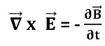
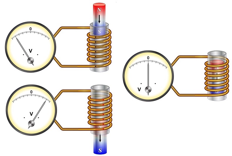
Induction Motor Working Priciple (Asynchronous Motor) The motor serves the purpose of converting electrical energy into mechanical form. Motors are categorized into AC motors and DC motors based on the type of power supply. In this post, we will talk about the different types of three-phase induction motors with working and applications. What is a 3 Phase Induction Motor? A three-phase induction motor is a type of AC induction motor that deals with a phase supply when diverged from the single-phase induction motor where the single-phase supply is supposed to work. The three-phase supply current makes an electromagnetic field in the stator winding which prompts the production of the torque in the rotor bending of the three-phase induction motor having a magnetic field. Next, we will be Going Through Faraday’s Law of Induction Motor. Faraday’s Law of Induction Motor Faraday’s law of electromagnetic induction is a significant decision that figures out the fundamental movement of a three-phase induction motor. It was sorted out by Michael Faraday and portrays the association between a changing magnetic field and the prompted electromotive force (EMF).
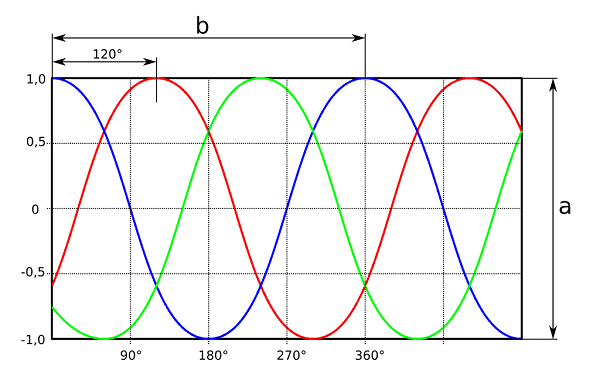
What is 3 Phase Power ? Three-phase power is a type of electrical power transmission or distribution wherein three sinusoidal voltages of a similar recurrence are produced or utilized. It is a typical strategy utilized in electrical systems, industrial systems, and huge electrical motors. The three-phase system is more proficient and gives a more steady power supply contrasted with a single-phase system.
Figure 1 - Three phase wave Here are the key components and attributes of three-phase power:
Construction of 3 Phase Induction Motor The construction of an induction motor is exceptionally basic and robust. It has predominantly two sections :
Figure 2 - Induction motor Stator of 3 Phase Induction Motor As the name recommends, the stator is a fixed piece of the motor. The stator of the induction motor comprises three primary parts;
Stator Casing The stator outline is the external piece of the motor. The stator outline can offer help to the stator core and stator winding. It gives mechanical strength to the inward pieces of the motor. The casing is balanced on the external surface for heat dissemination and cooling of the motor. Stator Core The stator core’s function is to carry the alternating magnetic flux, leading to hysteresis and eddy current losses. To limit these losses, the core is coated with high-quality steel stampings with a thickness ranging from 0.3 to 0.6 mm. Stator Winding The stator winding is positioned within the available spaces inside the stator core. The stator winding consists of three phases, and a three-phase power supply is provided to it. Ns = 120f / P Where; f = Supply Frequency P = Total Number of Poles Ns = Synchronous Speed As the end of winding connected with the terminal box. Consequently, there are six terminals (two of each phase) in the terminal box. As per the application and sort of turning over techniques for motors, the stator winding is associated in star or delta and it is finished by the association of terminals in the terminal box. For more details see Figure 3
Figure 3 - Stator and Rotor Rotor of 3 Phase Induction Motor As the name proposes, the rotor is a rotating part of the motor. As indicated by the type of rotor, the induction motor is delegated:
The development of the stator is the same in the two kinds of induction motors. We will examine the kinds of rotors utilized in 3-phase induction motors in the accompanying part of types of three-phase induction motors. Types of 3 Phase Induction Motor Three-phase motors are arranged mainly in two classes in light of the rotor winding (Armature coil winding) for example squirrel cage and slip ring (wound rotor motor).
Squirrel Cage Induction Motor The condition of this rotor is seeming to be the condition of the enclosure of a squirrel. As a result, this motor is referred to as an induction squirrel cage motor. This kind of rotor is easy to make and durable to make. In this way, basically 80% of the induction motor is a squirrel confine induction motor. See Figure 4 below
Figure 4 - Squirrel Cage Induction Motor The covered centre of the rotor is shaped like a tube, and the outside edges have spaces. The spaces are not equivalent anyway it is skewed eventually. It helps with magnetic locking between the stator and rotor teeth. It achieves smooth action and diminishes the mumbling commotion. Because it increases the length of the rotor guide, the rotor resistance gets bigger. Advantages
Disadvantages
Slip-Ring or Wound Rotor Induction Motor Slip-ring Induction Motor are generally called wound rotor motor. The rotor is made up of a tube-shaped center with slots on the outside edges. The rotor winding is placed inside the slots. In this type of rotor, the winding is arranged in such a way that the number of rotor winding slots matches the number of stator winding poles. The rotor winding can be related as a star or delta. The slip-rings are connected to the end terminals of the rotor windings. As a result, it is referred to as a slip-ring induction motor engine. The external block can without a doubt interact with the rotor circuit through the slip-ring and brushes. Likewise, it is uncommonly useful for controlling the speed of the motor and dealing with the starting force of the three-phase Induction Motor. For more details see Figure 5 below
Figure 5 - Slip-Ring or Wound Rotor Induction Motor The outside opposition is used solely for the starting reason. The rotor copper loss will be increased if it remains connected while the system is operating. For the initial condition, a high rotor resistance is extremely advantageous. During the initial state, the rotor circuit is linked to the outside resistance in this manner. The metal collar short-circuits the slip rings when the motor is running close to the actual speed. By this arrangement, the brushes and outside obstruction are taken out from the rotor circuit.
Advantages
Disadvantages
Working Principle of 3 Phase Induction Motor The stator winding is covered at 120˚ (electrically) to one another. When the stator winding is supplied with a three-phase power source, it results in the induction of a rotating magnetic field (RMF) within the stator circuit. Here, the rotor current is created because of inductance. Hence, this motor is known as the induction motor. Why the slip is never zero in an induction motor? When the rotor’s actual speed matches the synchronous speed, the slip is zero. However, in the case of an induction motor, this scenario is never encountered. This is because, at zero slip, both speeds are equivalent, resulting in no relative movement. Consequently, no electromotive force (EMF) is induced in the rotor circuit, and the rotor current becomes zero. As a result, the motor cannot operate. Despite this limitation, the induction motor is extensively used in industries due to its numerous advantages outweighing its disadvantages. Advantages of 3 Phase Induction Motor
Disadvantages of 3 Phase Induction Motor
Applications of 3 Phase Induction Motor
Conclusion In conclusion, the three-phase induction motor stands as fundamental equipment and is broadly used in electrical machines in different industrial applications. Its robust design, simplicity, and efficiency make it a favoured decision for controlling a huge number of devices, from pumps and fans to conveyer systems. The motor’s operation depends on the principles of electromagnetic induction, where the cooperation between the stator and rotor magnetic fields induces a rotating motion.
|


|
Single-phase, two-phase and three-phase motors Electric motors let us obtain mechanical energy in the simplest and most efficient manner. Depending on the number of supply phases, we can find single-phase, two-phase and three-phase motors with coiled startup winding and with coiled startup winding with a capacitor. And choosing one or the other will depend on the necessary power. What is a single-phase motor? A single-phase motor is an electrically-powered rotary machine that can turn electric energy into mechanical energy.
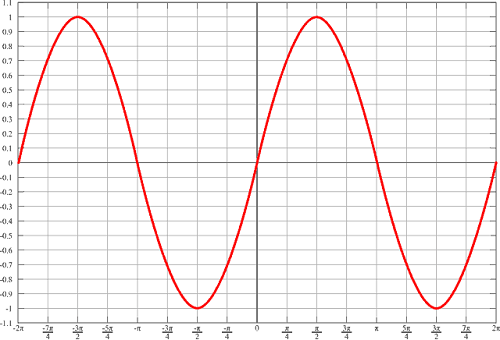
Figure 1 - sine curve on single phase motor In most cases these are small motors with a limited torque. However, there are single-phase motors with a power of up to 10 hp that can work with connections of up to 440V. What is a two-phase motor? A two-phase motor is a system that has two voltages 90 degrees apart, which is no longer in use nowadays. The alternator is composed of two windings placed at 90 degrees from each other. What is a three-phase motor? A three-phase motor is an electric machine that transforms electric power into mechanical energy by means of electromagnetic interactions. Some electric motors are reversible – they can transform mechanical energy into electric power acting as generators.
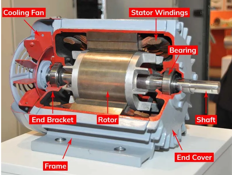
Figure 2 - sine curve on three phase motor Three-phase electric power is the most common method in use in electric grids around the world since it transfers more power, and it sees significant use in the industrial sector. After a general explanation we go into specifics What is a 3-Phase Motor? A 3-phase motor is an electric motor that operates on a three-phase power supply, utilizing three alternating currents to generate a rotating magnetic field, resulting in a smoother and more efficient power delivery compared to single-phase motors. They are a type of AC motor that is a specific example of a polyphase motor. These motors can be either an induction motor (also called an asynchronous motor) or a synchronous motor. The motors consist of three main components – the stator, the rotor, and the enclosure.
Figure 3 - Motor internal parts How Does a 3-Phase Motor Work? A 3-phase motor works by harnessing three alternating currents to produce a rotating magnetic field, which, in turn, drives the motor’s rotor and induces rotation. This design enhances efficiency and performance, making 3-phase motors suitable for a wide range of industrial applications.
These principles form the basis for understanding how a three-phase motor works.
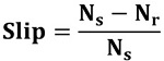
Figure 4 - Principle of Electromagnetic Induction For induction motors, when the stator is powered from a three-phase electrical energy source, each coil generates a magnetic field whose poles (north or south) change position as the AC current oscillates through a complete cycle. Since each of the three phases of the AC current are phase-shifted by 120o, the magnetic polarity of the three coils are not all identical at the same instant of time. This condition results in the stator producing what is known as an RMF or Rotating Magnetic Field. As the rotor sits in the center of the stator coils, the changing magnetic field from the stator induces a current in the rotor coils, which in turn results in an opposing magnetic field being generated by the rotor. The rotor field seeks to align its polarity against that of the stator field, the result being a net torque is applied to the motor shaft and it begins to rotate as it seeks to bring its field into alignment. Note that in the 3-phase induction motor, there is no direct electrical connection to the rotor; magnetic induction causes the motor rotation. With three-phase induction motors, the rotor seeks to maintain alignment with the RMF of the stator, but never achieves it, which is why induction motors are also called asynchronous motors. The phenomenon which causes the rotor speed to lag the speed of the RMF is known as slip, as is expressed as:
where Nr is the speed of the rotor, and Ns is the synchronous speed of the rotating field (RMF) of the stator. Synchronous motors operate in a similar fashion to induction motors except that in the case of a synchronous motor, the stator and rotor fields are locked into alignment so that the stator RMF will cause the rotor to turn at the exact same rate of rotation (in synch – therefore the slip is equal to 0). For more information on how this is accomplished, refer to these articles on reluctance motors and brushless DC motors (BLDC motors). Note that synchronous motors, unlike induction motors, need not be powered by AC power. Motor Controllers for 3-Phase Motors The speed that is generated by a three-phase AC motor is a function of the AC supply frequency since it is the source of the RMF in the stator coils. Therefore, some AC motor controllers operate by using the AC current input to generate a modulated or controlled frequency input to the motor, thereby controlling the speed of the motor. Another approach that can be used to control motor speed is by altering the slip (described earlier). If the slip increases, the motor speed (i.e. the speed of the rotor) decreases. To learn more about the approaches for motor control, review our article on AC Motor Controllers. 3-Phase Motor Types There are several types of 3-phase motors, each designed for specific applications:
When Would a Three-Phase Motor Be Used? A three-phase motor would be used in various applications, including:
|

+(39) 347 051 5328
Italy - Kazakhstan


09.00am to 18.00pm
About
We offer the best and economical solutions, backed by 27+ years of experience and international standards knowledge, echnological changes, and industrial systems.
Our Services
Marketing Materials


Marketing Materials1


