

This product ships globally
SKU
:
DUA-631-MD-001
In Stock
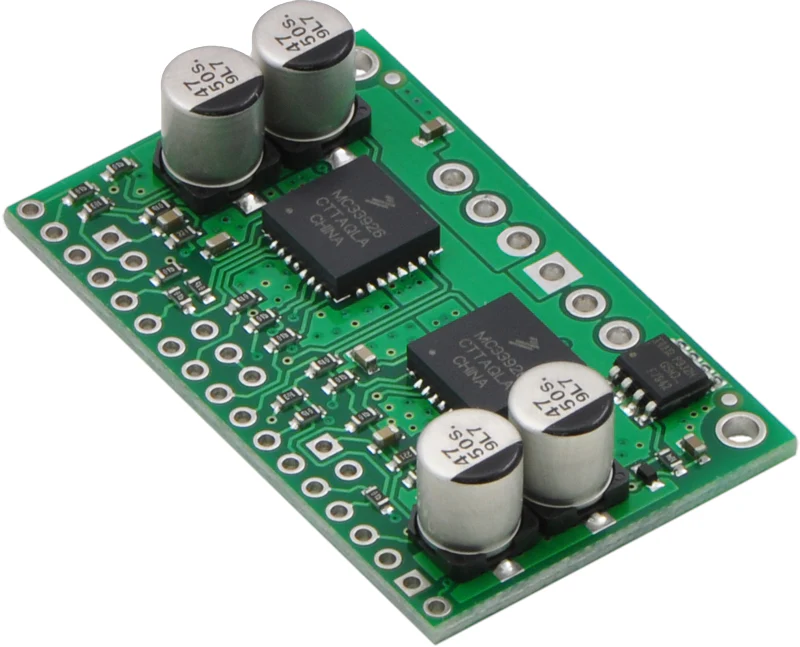
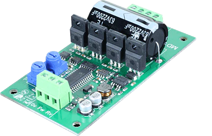
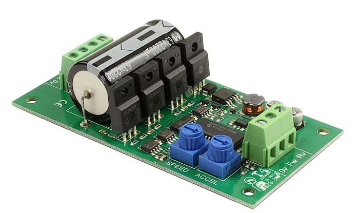
MD22 - Dual 24Volt 5Amp H Bridge Motor Drive
$69.87
Model
:
MD225A
Quantity
Social share:
Social share:
You have 30 days to ask for a refund. All things on sale are final sale.
MD22 - Dual 24Volt 5Amp H Bridge Motor Drive
| Technical Specifications: | |
| Voltage | 5v logic supply and 5v - 24v for the motor |
| Current | 50mA Max for logic and up to 5A for each motor |
| Dimensions | 110 x 52 x H 25 mm |
Overview
The MD22 is a robust low/medium power motor driver, designed to supply power for two motors. Main features are:
1. Drives two motors with independent control.
2. Ease of use and flexibility.
3. The 15v MOSFET drive voltage is generated onboard with a charge pump, so the module requires only two supply voltages;
a) A standard 5V supply for the control logic, only 50mA maximum is required.
b) Motor voltage, anything up to 24vdc to suit your motors.
4. Steering feature, motors can be commanded to turn by I2C register or input (Analogue + Servo).
5. Control of the module can be any of;
a) I2C bus, up to 8 MD22 modules, switch selectable addresses and 4 modes of operation including steering..
b) 2 independent 0v-2.5v-5v analog inputs. 0v full reverse, 2.5v center stop, 5v full forward.
c) 0v-2.5v-5v analog input for speed ,with the other channel for steering.
d) independent channel RC mode. Motors are individually Controlled directly from the RC receiver output.
e) RC mode with steering, allows speed control with one stick of radio control, and steering with the other.
6. Uses high current MOSFETs capable of much more than the 5Amp Specification.
They are capable of 27Amp continuous with a suitable heat-sink and up to 290Amps in very brief repetitive pulses. Without a heat-sink they can handle 5Amps continuously, hence our specification.
Note - There is no fuse on the PCB. You should provide a 10A fuse in line with the +v battery terminal. Don't Ignore this, High currents can be dangerous
The Motor Ground and the Logic Ground are internally connected on the Module. Be sure to use cable rated for at least 10A for the Battery, Fuse and Motor leads.
Mode Switches
The 4 mode switches set the operating mode of the MD22. They are read once only when the module is powered up. You cannot switch modes while the unit is on.
New Page 1
| Mode | Switch 1 | Switch 2 | Switch 3 | Switch 4 |
| I2C Bus - address 0xB0 | On | On | On | On |
| I2C Bus - address 0xB2 | Off | On | On | On |
| I2C Bus - address 0xB4 | On | Off | On | On |
| I2C Bus - address 0xB6 | Off | Off | On | On |
| I2C Bus - address 0xB8 | On | On | Off | On |
| I2C Bus - address 0xBA | Off | On | Off | On |
| I2C Bus - address 0xBC | On | Off | Off | On |
| I2C Bus - address 0xBE | Off | Off | Off | On |
| 0v - 2.5v - 5v Analog | On | On | On | Off |
| 0v - 2.5v - 5v Analog + Turn | Off | On | On | Off |
| RC Servo | On | Off | On | Off |
| RC Servo + Turn | Off | Off | On | Off |
| RC Servo - Timeout On | On | On | Off | Off |
| RC Servo + Turn - Timeout On | Off | On | Off | Off |
Note that I2C addresses are the upper 7 bits. Bit 0 the the read/write bit, so addresses 0xB0/0xB1 are write/read respectively to the same address. This range of I2C addresses is the same as those used by the MD03.
For more details download the datasheet here or download the sample routine here
Frequently Bought

+(39) 347 051 5328
Italy - Kazakhstan


09.00am to 18.00pm
About
We offer the best and economical solutions, backed by 27+ years of experience and international standards knowledge, echnological changes, and industrial systems.
Our Services
Marketing Materials


Marketing Materials1


