

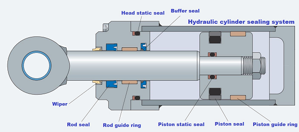
Buffer Seals
Buffer seals are usually located in front of the rod seals and serve as an extra line of defence in the event of an extreme spike in internal pressure. Preventing that pressure from reaching the rod seal and potentially blowing it out. Buffer seals also have a general regulatory effect on system pressure, ensuring smoother operation, better rod seal performance, and longevity by ensuring more gradual pressure buildup. Buffer seals also reduce the number of system contaminants such as metal particles that reach the rod seal, where they can do damage.
Rod Buffer Seal (Metric)
DYR-20004-BR43 Buffer Seal
MKR Buffer Seal Series

VME Buffer Seal Series (metric)

HIT Buffer Seal Series (metric)

JD Buffer Seal Series (metric)

KOB Buffer Seal Series (metric)

CTC Buffer Seal Series (metric)

DI Buffer Seal Series (metric)
FD Buffer Seal Series (metric)
MBRW Rod Buffer Seal Series (metric)
MYBR Rod Buffer Seal Series (metric)
MYR Rod Buffer Seal Series (metric)
KOM Rod Buffer Seal Series (metric)

KR Rod Buffer Seal Series (Inch)
how to order
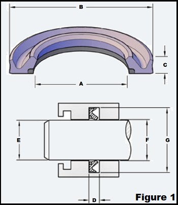
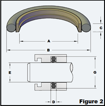
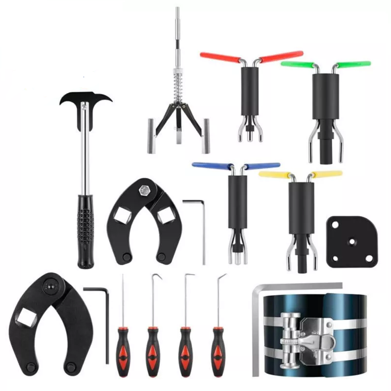
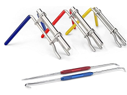
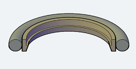
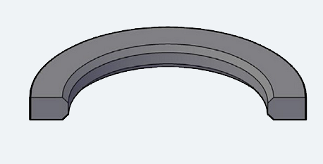
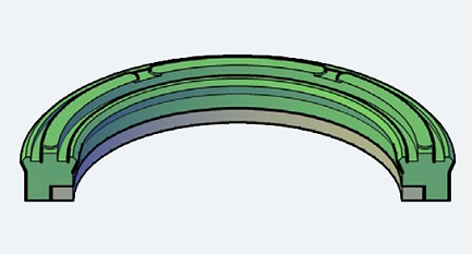
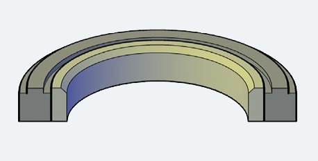
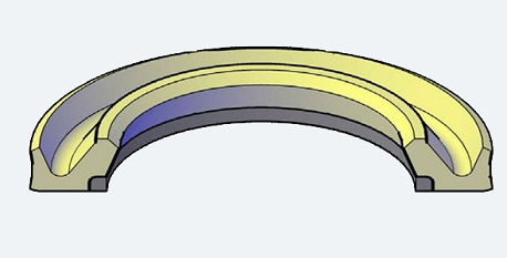
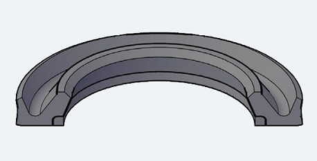
As you can see from Figures 1, 2, and 3, we have different models and also different measurements of the buffer seals. To send your request correctly, please where the letters are not present in the reference figure, write in the textbox 0.1 on the side ( buffer seals quotation)
How Buffer Rod Seals Influence Rod Seal Performance
- Buffer seals protect equipment against pressure spikes.
- The key factor with buffer seals is the thin film of oil it lets past.
- The main types of buffer seals are lip seals with back-up rings, lip seals without back-up rings and O-ring energized glide ring seals, each with their own performance characteristics.
Designers often specify buffer seals be placed in front of primary rod seals in heavy-duty hydraulic applications to extend the life of the seals. As the name indicates, buffer seals “absorb” pressure spikes typical on heavy-duty cylinders to protect the primary rod seals.
But how do these two types of seals interactions interact, which parameters affect those interactions, and how can they be used to extend the life of cylinder rod-sealing systems?
What was learned during these investigations will give engineers insights into seal types and interactions between seals so they can specify the most appropriate seals for their applications.
Find your Item: Choose your Buffer seal. For any other option please write in the comment below
The primary rod and buffer seals must:
- Prevent leaks by reducing lubrication film thickness and allow back-pumping into the system.
- Adjust lubrication film thickness so there are the fewest and smallest possible leaks and low friction.
- Absorb intermediate pressure.
And the wiper must:
- Keep out all kinds of environmental contamination.
- Prevent leaks by pumping lubricant back into the system.
- Vent intermediate pressure between rod seals and wipers
The key element of the buffer seal is the lubrication film thickness which passes the sealing edge. It is responsible for the performance of the entire rod sealing system. Different pressure and speed conditions during the in- and outstroke of the piston rod are typical for heavy-duty hydraulic cylinders and result in different oil film thickness. Therefore, the buffer seal needs to be designed to ensure a lubricated rod seal and absorb pressure peaks during operation.
Buffer Seal Designs
There are many different buffer seal designs and various material combinations available on the market. Here are the three most common designs.
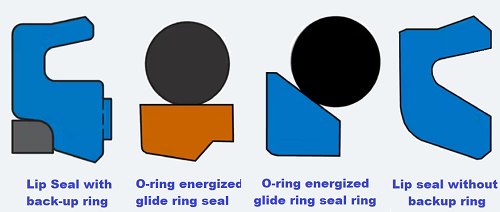
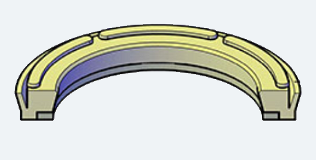
Lip seals without back-up ring
These are popular in Asia. This type of buffer seal has a radius on the seal lip to let oil past it. They are cost-competitive but are also as limited in pressure and extrusion resistance, and don’t perform as well at absorbing pressure spikes.
The buffer seal’s main task is keeping the lubrication film thickness that passes through the seal’s edge at the right thickness. According to the Reynolds equation, the flow of a thin film oil/lubricant between two surfaces is influenced by its velocity, the gradient of the contact pressure distribution and the oil’s viscosity.
An important aspect of the investigations was to understand lubrication behavior under different test parameters. The lubrication level of lubrication determines friction and is essential for seal life. On the other hand, the lubrication level also determines the number and size of leaks, which should be minimized for the sake of performance and environmental concerns.
The lubrication level is influenced by instroke and outstroke piston-rod velocity, seal design and the type of hydraulic oil used.
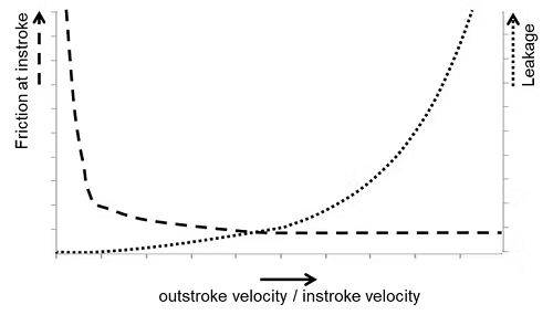
The influence of different in- and outstroke velocities has already been analyzed for a common U-Cup rod seal (see above graph). The results show that if outstroke velocity is much higher than instroke velocity, the likelihood of leaks increases. On the other hand, if instroke velocity is much higher than outstroke velocity, it is more likely the low-level of lubrication will increase friction on the instroke.
The second driver for the lubrication film thickness is contact pressure between the seal and piston rod. The higher the pressure gradient, the thinner the film. The gradient is influenced by seal design, the pressurization level, and the resulting deformation and dynamics between piston rod and seal.
The third driver for the lubrication film thickness is the lubricant’s viscosity. The lower the viscosity, the thinner the lubrication film.
High sealability
Buffer seals have good sealing abilities and can handle all of the system pressure and possible pressure peaks. Therefore, the primary rod seal will not be pressurized and can’t be damaged by pressurization. The seal’s high sealability means only a thin film of lubrication film can pass it, which could cause starve the primary rod seal of lubrication. This can lead to stick-slip, higher friction and sealing-edge temperatures, and possibly damage to the sealing material, all of which shorten the rod seal’s life.
Friction optimized
buffer seals let thicker oil film pass the sealing edge to properly lubricate the primary rod seal. Depending on operating conditions, they can also let pressure build-up between the primary rod and buffer seals (intermediate pressure).
These buffer seals should keep out system pressure, because if the intermediate pressure is equal to system pressure, it cannot buffer. It is also important to use a primary rod seal and a wiper for good sealing and back-pumping ability to guarantee a leak-tight system.
An additional advantage of this type of seal is that the primary rod seal gets better lubrication, leading to smooth running equipment. If the buffer and primary rod seal work together correctly (as described above), friction in the entire rod sealing system can be similar to that of a single rod seal component. Reducing friction extends the life of the rod seal and the entire hydraulic cylinder.
Both working concepts have their place. Friction optimized buffer seals might be best in OEM components to extend a hydraulic cylinder’s service life. But high-sealability buffer seals might be more suitable in the aftermarket, where repair work and maintenance on hydraulic cylinders is more common and a leak-tight rod seal is more important.
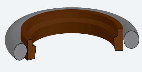
Lip seals with back-up rings.
These seals are good in heavy duty applications, where pressure spikes climb past 600 bar. The best lip seals are made of polyurethane with a thermoplastic back-up ring. This design enjoys a longer service life because the back-up ring resists extrusion. On the other hand, the back-up ring can influence the motion of the film of fluid on the piston rod, and seal installation requires more attention.
O-ring energized glide ring seals
These seals are widely used in light- to medium-duty application. Generally, the O-ring acts as an energizer to push the glide ring towards the piston rod. A big advantage of this is that various materials can be used. For example, a low temperature rubber grade can be used for cold climate conditions. The various material combinations give designers a wide choice. These seals have less resistance to extrusion compared to those with back-up rings.
Test Results Compare Buffer Seals for Hydraulic Cylinders
- Testing determines which factors affect buffer seal performance.
- The wrong seal in an application can be damaged.
- It is critical that designers check out their applications’ operating parameters before selecting a buffer seal.
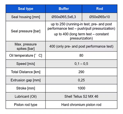
To examine and compare the two most common types of buffer seals—high-sealability and friction optimized seals—and the parameters that extend their service lives, our team developed a test rig that covers all application parameters to get an overview on seal performance.
What was learned during these investigations should help engineers understand the seal types and the interactions between seals so they can better specify the most appropriate ones for their applications.
 For more details about this test, please click here
QC & Certificates
Our mature strict quality control team will check the products before shipment, including quality, prints, package, instruction manual and Certificate: ISO9001:2008, ISO/TS16949:2009
Safe Packaging
Our package is according to the seaworthy Packing Way in International Trade. We use good quality Poly bag and Master Carton for items. About more details, please send enquiry to us.
Free Sample in 5 Days
After confirming sample model and design, we can send the samples by your courier account like FedEx and DHL etc. About the samples details, please send inquiry for more .
Our Shop
ABOUT US
Bennypass is a multi-generational company, operating since 1998. For more than 27 years, we have been growing steadily, gaining experience and becoming one of the most dynamic global distributors of electronic and electrotechnical components, workshop equipment and industrial automation solutions. Our business is a global one, but we remain a family company. We believe that a positive working atmosphere, flexibility and individual approach to each client allow us to achieve the best results.
Our knowledge


Calculating O-Ring Cord Cut-Length
How to calculate O-Ring cord length needed: ( ( OD + ID ) / 2 ) x Pi = length Pi=3.14159 Inside Diameter (ID) = Outside Diameter (OD) - twice the cross section (C/S) ID = OD - (2 x C/S)