
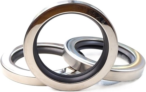
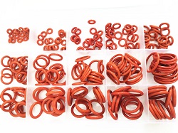
Gamma Seal
The GAMMA seal is the result of a large›scale development project covering many years of attempts to combine the capability of conventional mechanical seals to operate at high speeds with the simplicity of the Rotary Shaft Lip Seal. Figure 8 shows the different types. which are characterized by simple design. The basic design consists of two parts, sealing element and metal case. The GAMMA seal is designed to be fixed to the shaft at a pre-determined distance from the sealing surface, which is positioned perpendicularly to the shaft, for example the end wall of a bearing housing. During rotation, the sealing lip rubs against the counter face under a contact pressure calculated to achieve a sealing function.
The seal also operates as a deflector ring, and its centrifugal action contributes to good sealing function. Due to the effect of centrifuga! force, the sealing lip tends to reduce its contact pressure with increasing speed. As a result, the curve for power loss is very favorable (see Figure 2). At a peripheral speed of around 12 m/s, friction losses begin to diminish and cease completely at about 20 m/s, when the sealing lip nas completely lifted free of counter faces. The GAMMA seal then functions as a combined deflector ring and clearance seal.
How do Gamma Seal work?
The GAMMA seal permits simple installation design and the requirements on the surface against which the sealing lip works are low. A finish›turned, polished surface with a roughness of 3 - 5 um Ra is normally adequate. However, the character of the surface is of greater importance than the action surface roughness value. Surface profiles with sharp peaks must be avoided. Injection-molded light-metal alloys can be used in counterfaces without further machining. lt is necessary to ensure, however, that the part of the mould that produces the counter face is absolutely flawless.
Cold-rolled steel sheet, stainless or zinc plated sheet are excellent materials for counter faces for GAMMA seal. In comparison to other types of seals, the GAMMA seal can better absorb a certain amount of shaft misalignment. lt is also relatively insensitive to shaft-tdbore eccentricity and shaft run-out. Directions of shaft design and fitting are provided in the following sections on GAMMA seal types TBP/RB and TBR/9RB.
GAMMA SEAL TYPE TBP/RB AND TBR/9RB
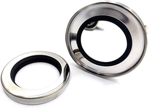
GAMMA seal type TPB/RB and TBR/9RB consists of an elastic sealing element and a metal case (see Figure 3). The case serves as a holder, support and protection for the sealing element and constitutes a very effective deflector. The components are not bonded to each other, the rubber-sealing element is stretched and held in the case by its elasticity.
Type TBP/RB and TBR/9RB provide a very narrow installation width, which has proved to be very advantageous in certain applications and has permitted this seal to be used in assemblies where other seals could not previously be installed due to lack of space. The seal is press fitted on the shaft, and no other means of fixing is required.

Figure 3 - Gamma Seal Type

Figure 2 - power loss as function of peripheral speed
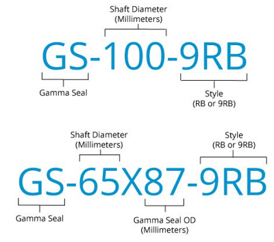
Gamma Seal Part Number System
Seal’s Gamma (Seal part numbers) are designed to describe the Shaft Diameter and Gamma Seal Outside Diameter (in millimeters) and style. We utilize two naming conventions which are shown in the examples below. The first example shows a Gamma Seal accommodating a Shaft Diameter of 100mm, with a 9RB style. The second example shows a Gamma Seal with an Outside Diameter of 87mm, accommodating a Shaft Diameter of 65mm, with a 9RB style.
Gamma Seal Installation
INSTALLATION DESIGN
GAMMA seal type TBP should normally be installed as shown in Figure 4, i.e. with the seal located in the medium which it is to seal against. As shown in Figure 8 the counter face for type TBR against which the sealing lip works should be designed with a groove for the case extension in order to create the ciearance seal. For vertical shafts a design in accordance with Figure 5 is preferred, which effectively will reject impurities and liquid splatter. Shaft tolerance ISO h9 provides a suitable press fit. The shaft tolerances normally used for ball and roller bearings, ISO g6 to n6, can also be used. The seal does not require any other axial fixing other than that which is obtained by the press fit between the case and the shaft.
MANUFACTURING MATERIALS
The sealing element is moulded and is normally made of Nitrile rubber with a hardness of 75 15 IRHD. Other compounds can be supplied on request. The case is stamped of a cold-rolled steel sheet. in order to ensure a good seal and a tight grip on the shaft, the inside diameter is machined to dimensions which ensure a suitable press fit. The tolerances for the inside diameter of the case are given in Table 1 below. The case is normally zinc-plated. The case can also be made out of other materials, such as stainless steel.
Seal Installation including Lead-in Chamfers Table
Prior to being fitted, the sealing member shall be greased, but not between the sealing member and the case. It is important that the seal is fitted with adequate precision. The seal shall be pressed onto the shaft with a uniform and even pressure. The case must not be tapped directly with the hammer. The seal should therefore be pressed to the right position by means of a suitable assembly tool (see Figure 7, Figure 8 and Figure 9). Since facial fixing beyond the press fit between the seal and the shaft is not provided, the assembly tool should be of a design as shown in Figure 7 and Figure 9 in order to obtain the installation width b as per the dimension tables. The surface roughness of the shaft should not exceed 4 um Ra. In addition, the shaft should be provided with a chamfer as per Figure 3a. Sharp edges or burrs are not permitted. In the case of width b, a variation of +O.5 mm is permissible.
The lead edge of the shaft and lead corner of the seal bore should have a chamfer or radius to prevent damage to the sealing element and for ease of installation.
- Sealing lips must always face the medium to be sealed. The lips should be absolutely free and never tilted or pinched.
- Seal lip contact area on the shaft should be smooth and must be defect free.
- Seals must be installed concentrically and perpendicularly to the shaft, the use of suitable installation tools is recommended.
- Seals must not be axially deformed and must never be used to transmit forces.
- Silicone rubber seals need special attention because of their poor impact strength.
- To obtain a solid installation, Seal's outer diameter must larger than bore diameter, suggested as the following table.
Note: For Seals having grooved outer surfaces, additional interference allowances are to be agreed upon
| Table 1 - Lead-in Chamfers | ||
| Inside Diamter - mm | Chamfer - mm | Tolerance - mm |
| 0 - 35 | 2 | -0.15 / 0.25 |
| 36 - 50 | 2 | -0.18 / -0.28 |
| 51 - 135 | 2 | -0.20 / 0.30 |
| 136 - 200 | 2 | -0.25 / 0.35 |
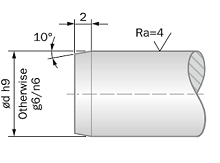
Figure 3A - tollerance of the shaft
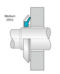
Figure 3B - Installation Drawing

Figure 4 - Horizontal Installation

Figure 5 - Gamma-Seal-Vertical

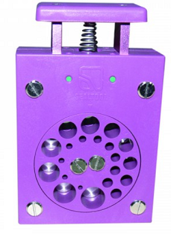
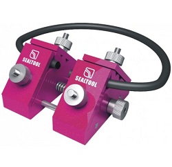
Figure 6 - Gamma-Seal-Installation-A.Tool

Figure 7 -Assembly Tool for TBP/RB

Figure 8 - Assembly tool TBR/9RB

Figure 8 - Assembly tool when positioning seal against
Installation Checklist
- Check the bore. Remove any burrs from the leading edge. The inside corner of the bore should have a maximum radius of .031" (0.78mm).
- Check the shaft. Remove burrs, nicks, grooves and spiral machine marks (machine lead).
- Check the shaft end. Remove burrs or sharp edges. If the shaft enters the seal against the sealing lip, the end must have a radius or chamfer or a special installation tool can be used.
- Check splines and keyways. Sharp edges should be covered with a lubricated assembly sleeve, shim stock or tape to protect the seal lip.
- Check the dimensions. Make sure that shaft and bore diameters match those specified for the seal being used.
- Check for part interference. Watch out for other machine parts that might rub against the seal and cause friction and damaging heat.
- Check the seal. Damage may have occurred before installation. A sealing lip that is turned back, cut or otherwise damaged should be replaced.
- Check seal direction. Make sure the new seal faces in the same direction as the original one. Generally, the lip faces the lubricant or fluid being retained.
- Pre-lubricate the sealing element. Before installation, wipe the sealing element and shaft with the lubricant being retained. While the O.D. of a metal-clad seal can be lightly lubricated to ease installation, the O.D. of a rubber-covered seal should always be lubricated.
- Select the correct installation tool. Press-fitting tools should have an outside diameter approximately 01 0" (.25mm) smaller than the bore size. For best results, the center of the tool should be open so the pressure is applied only at the seal outer edge.
- Never hammer directly on the surface of the seal. Use proper driving force such as a soft-face tool arbour press or soft workpiece (wood). To avoid cocking the seal, apply force evenly around the outer edge.
- To avoid cocking the seal, bottom out the tool on the shaft (Fig.7), the housing (Fig.8) or bottom out the seal in the housing cavity (Fig .9).
Gamma Seal Size Charts
Advance RB Series Seals
ADVANTAGES
- Good dynamic seaiing
- Very good protection against solid pollution particles
- Modern lip design provides low axial forces (low power loss)
- Small fitting width
- No supplementary retention's needed
APPLICATION EXAMPLES
- Transmission systems (e.g. gearboxes)
- Pumps
- Electrical motors
- Machine tools
- Wheels and heavy-duty axles
Advance RB9 Series Seals
ADVANTAGES
- Good dynamic sealing
- Very good protection against solid pollution particles
- Modern lip design provides low axiai forces (low power loss)
- Small fitting width
- No supplementary retention's needed
- Very effective supplementary labyrinth protection
APPLICATION EXAMPLES
- Transmission systems (e.g. gearboxes)
- Pumps
- Electrical motors - mixers
- Machine tools
- Wheels and heavy-duty axles
Question and Answer: Submit Your Question Below!
For Business: For any questions regarding Gamma Seal, please fill out our feedback below.
Our Partners


QC & Certificates
Our mature strict quality control team will check the products before shipment, including quality, prints, package, instruction manual and Certificate: ISO9001:2008, ISO/TS16949:2009
Safe Packaging
Our package is according to the seaworthy Packing Way in International Trade. We use good quality Poly bag and Master Carton for items. About more details, please send enquiry to us.
Free Sample in 5 Days
After confirming sample model and design, we can send the samples by your courier account like FedEx and DHL etc. About the samples details, please send inquiry for more .

+(39) 347 051 5328
Italy - Kazakhstan


09.00am to 18.00pm
About
We offer the best and economical solutions, backed by 27+ years of experience and international standards knowledge, echnological changes, and industrial systems.
Our Services
Marketing Materials


Marketing Materials1


