
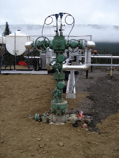
Onshore Production Wellhead
Crude Oil extraction methods The exploitation of the well # is caused by the reservoir pressure being greater than the weight of the hydrocarbon column from the reservoir to the wellhead. This pressure, which allows the exploitation of the well, can be of three types, that is:
These natural push mechanisms often coexist. Primary extraction methods, i.e. methods based on the exploitation of the natural expulsion forces that push the oil from the reservoir rocks to the extraction wells, are generally not very efficient. Often a large part of the original oil remains in place, in fact as the delivery proceeds the volume and pressure of the gas produced decrease until reaching a reservoir pressure such as to be insufficient for the fluid to reach the surface. Primary extraction methods allow for the recovery of a very low percentage of oil which actually is present, sometimes this percentage is just 10% and rarely exceeds 50%. Therefore the quantity of oil extracted is 1/3 of the total. This vast reserve (remaining 2/3) of oil stimulates the search for increasingly efficient recovery of the remaining oil. There are many methods:
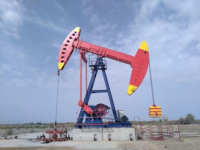
Beam-Balanced Pumping
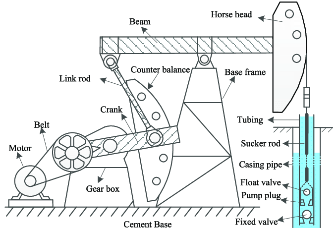
Delivery is made by a pump placed in the tubing at a variable depth which depends on the dynamic level of the oil in the well. The piston of the pump is connected by rods to a balance wheel installed at the wellhead which is driven by an electric or petrol engine. Thanks to a reducer placed between the engine and the balance wheel it is possible to regulate the speed, therefore the number of piston strokes per minute, corresponds to the flow rate of the well. It is clear that the downward stroke of the piston and rods occurs by the free fall of the piston itself, therefore the pumping speed is conditioned by the fall speed of the piston-rod system. This must therefore always be greater than the pumping one. Fig.3 represents the internal parts in a pumping stand.
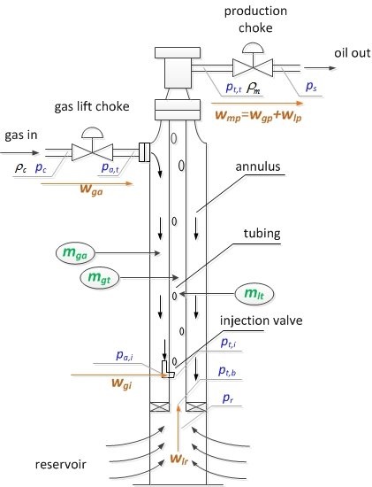
GAS-LIFT This method consists in allowing gas to enter the tubing from the casing, at a certain depth, which will push the oil to the surface. The insufflation of gas takes place through valves mounted along the tubing at regular intervals, in a variable number from 2 to 7. The opening mechanism is regulated by the injection of gas at established pressure. The most used methods for the extraction of oil by using the "GAS-LIFT" are two:
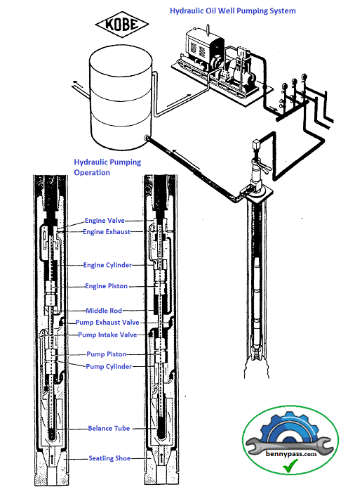
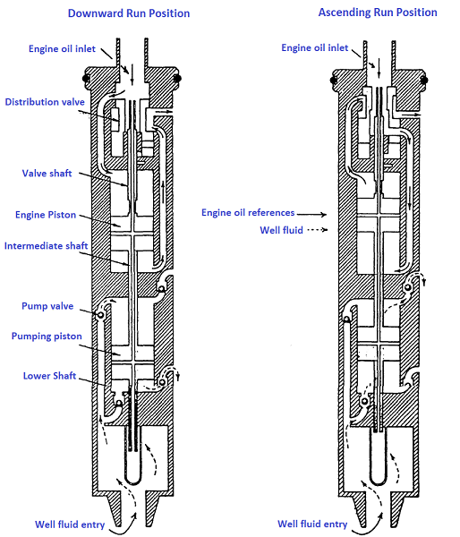
Hydraulic pumping (KOBE submersible pump) It is an artificial lifting system in which a submersible pump is operated by pressurized hydraulic oil. As you can see in Fig.5, it consists of a surface pump, a storage tank for the driving fluid, a control station and a submersible pump located in the tubing. This submersible pump (Fig.5A) consists of a "motor" and a "production pump" combined in the same assembly. The driving fluid is pumped back to the surface together with the fluid and sent to the tank. Production can take place behind the tubing or via a second tubing. Installation and removal are done with WIRE-LINE operation.
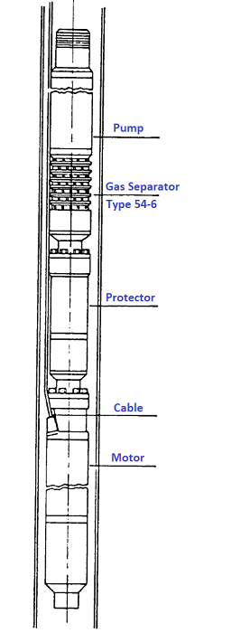
Submersible electric pumps (REDA) They are multistage centrifugal pumps, whose shaft is directly connected to the submersible electric motor. The entire complex can be directly immersed at the desired depth (directly in the well fluid). The pump and the motor are built to reach a depth of up to 5000 meters. Generally as shown in Fig.6, the system consists of:
English Terminology of Pumping Units
|


+(39) 347 051 5328
Italy - Kazakhstan


09.00am to 18.00pm
About
We offer the best and economical solutions, backed by 27+ years of experience and international standards knowledge, echnological changes, and industrial systems.
Our Services
Marketing Materials


Marketing Materials1


