Storage and Shipping
Storage
In the Oil Fields, storage is carried out using vertical cylindrical tanks which can have a fixed roof (see Fig.27), or a floating roof (see Fig.28). Since the tanks are very expensive equipment, very important also the storage capacity, i.e. the dimensions of each individual tank and the number of them, also must be established by careful studies on the field's production capacity and shipping capacity.
Normally, to ensure production continuity and independence between production and the shipping schedule, there are three tanks: the first is being filled, the second should be fully and awaiting customs clearance, and the last is being shipped.
A crude oil Tank, contains several tons of flammable product, and it constitutes a considerable risk, for this reason, it must be equipped with suitable safety equipment.
Each tank is inserted in a containment basin made of reinforced concrete capable of containing the entire volume of liquid in the event of tank failure.
The fire-fighting system includes rings for cooling the external surface with water and a fixed foam system. Fixed roof tanks are suitable for the storage of very stable products, i.e. with low volatility.
In the Oil field, on the other hand, they are used as the last separation at atmospheric pressure to remove any residual gas which is still dissolved in the oil. The stabilization of the oil is obtained by keeping the pressure inside the tanks at very low values (max 20 mmH2O), i.e. at the minimum pressure necessary to send the released gas to the flare. On the other hand, in floating roof tanks, the roof rests on the oil, in this case, avoid to evaporation losses.
With some petroleum products, these evaporation losses are quite substantial with consequences that result in economic loss.
For LPG storage, spherical tanks equipped with a safety valve are used (Fig.31). In these tanks, a pressure of 3 to 4 bar is maintained. (PSV open value: 11 bar)
They are equipped with a fixed fire-fighting system, and consisting of an external cooling ring and a line which introduces water from the lower part of the sphere. Also in this case is present a containment basin with adequate proportions with more gas detectors near each sphere.
Misura
In the Oil fields, it is necessary to carry out the measurement (every day) of the oil quantity present for fiscal reasons and also to know the daily production.
The level survey occurs through the tank calibration tables, which provide the quantity in volume. For conversion in tons, it is necessary to know the specific weight of the product.
Therefore, before each shipment, a sample of the product is taken and analyzed. The sample is taken at three different levels and then mixed to obtain a measurement of a homogeneous product sample.
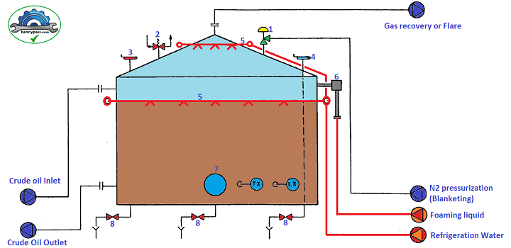 Figure 27 - Storage Tank with the fixed roof Figure 27 - Storage Tank with the fixed roof
Elements
- Pressurization valve
- Breathing valve
- Safety valve
- Manual Level Meter
- Cooling line (FireWater)
- Foam pourer
- Porthole
- Drain Valve
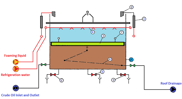 Figure 28 - Storage Tank with floating roof Figure 28 - Storage Tank with floating roof
Elements
- Foam Generator
- Foam pourer
- Floating Roof
- Refrigeration Water Ring
- Bottom drainages
- Roof drainage
- Foam Containment Ring
Figure 28A shows a Storage tank with a Floating Roof
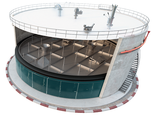 Figure 28A - Storage tank with Floating Roof Figure 28A - Storage tank with Floating Roof
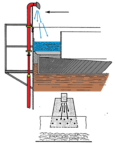 Figure 29 - Foam Pourer for Floating Roof Tank Figure 29 - Foam Pourer for Floating Roof Tank
Figure 30 below shows the arrangement diagram of foam channels for the protection of floating roof tanks
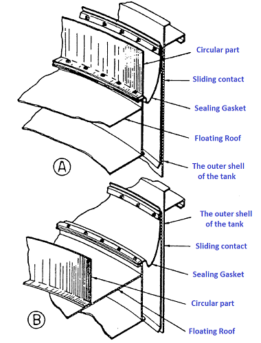 Figure 30 - Tank Roof Schematic Figure 30 - Tank Roof Schematic
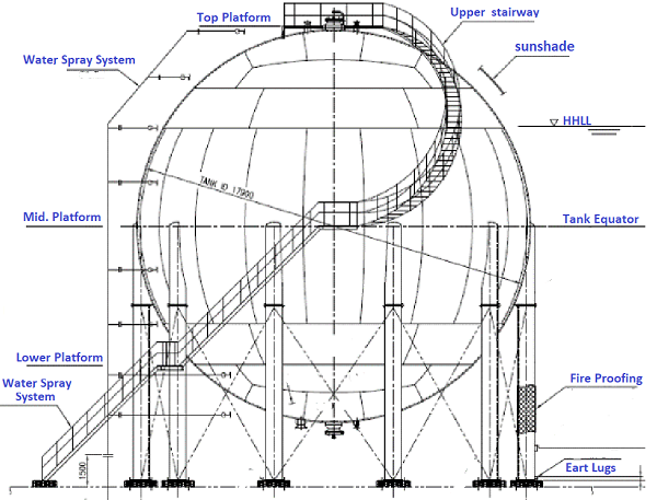 Figure 31 - LPG Storage Tank Figure 31 - LPG Storage Tank
Figure 31A shows a classic spherical Storage Tank for LPG
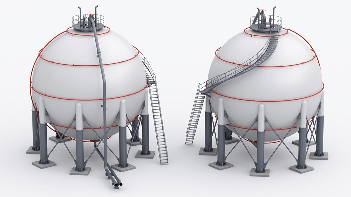 Figure 31A - Spherical Storage Tank Figure 31A - Spherical Storage Tank
Shipping
From the storage tanks, the treated oil goes in suction to the booster pumps (auxiliary pumps). These pumps normally are centrifugal type and driven by an electric motor.
From the booster pumps the crude Oil is transferred to the Delivery Pumps which will inject the crude into the pipeline. Also, these Pumps normally are driven by an electrical Motor.
The reason why it is necessary to install booster and Delivery pumps in series derives from the fact that, as the liquid head available on the pumps is very limited (low pressure), the transfer pumps may not be able to operate at their best.
Generally, the pumping system is realized through pumps in parallel (see Fig.32) or in series (see Fig.32A). Parallel pumps are used when highly variable flow rates are expected. Series pumps are mainly used when there are high flow rates and transfer pressures. In this case, the delivery pressure of each pump is added to the others, while the total flow rate is the same as the first pump.
The output pressure from a pipeline Oil is given by the flow rate that should be transferred. Each pipeline, therefore, has its own characteristic flow/pressure curve.
Fig.33 shows a characteristic flow rate/pressure curve of a typical pipeline. However, the Delivery pumps must be able to supply the pressure needed to send the product to each operating point of the pipeline.
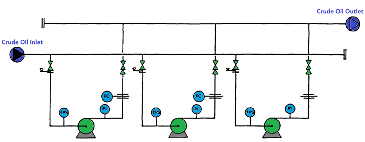 Figure 32 - Pumps Parallel Connection Figure 32 - Pumps Parallel Connection
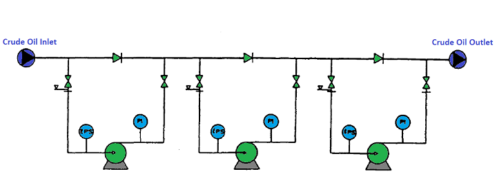 Figure 32A - Pumps Series Connection Figure 32A - Pumps Series Connection
Figure 32B Figure 32C shows a classic Installation of the Booster and Delivery Pump, including all protection
 Figure 32B - Classic Connections of Booster Pumps Figure 32B - Classic Connections of Booster Pumps
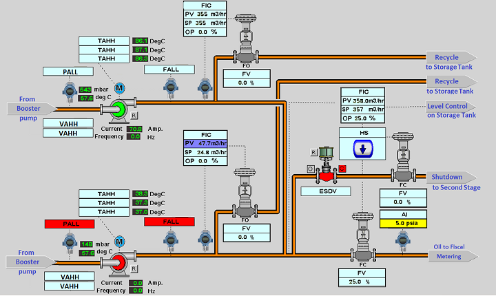 Figure 32C -Classic Connections of Delivery Pumps Figure 32C -Classic Connections of Delivery Pumps
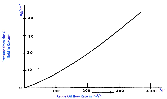 Figure 33 - Flow Rate and pressure curve Figure 33 - Flow Rate and pressure curve

|


