
Water treatment plant
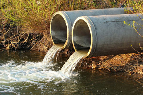
The layer water coming from the production separators, having been in close contact with the oil, for this reason, cannot be released outside from oil plant without prior purification. Purification consists of the following operations
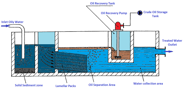
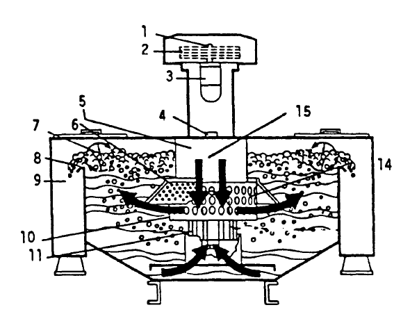
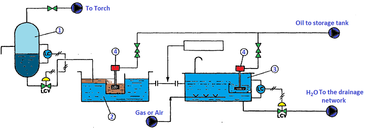
For Information: Part of the decantation already occurs in the production tank before the actual equipment. The filtration and separation take place in equipment called API Skimmers (see Fig.36), which consist of compartmented tanks where the oily water is scrolled slowly through lamellar filter packs, in this area the oil is separated from water and collected (recovered) and water is sent to the flotation unit. The API Skimmer guarantees outlet water with an oil content of 20 -/+ 40 ppm compared to 1000 o 10,000 ppm. before entering the skimmer. European law, to release water into the environment must be a maximum of 5 ppm of oil only, so as the API Skimmer is not sufficient, the water is treated in the flotation unit (see Fig.37), a device where the oil removal through by air injection in the presence of foaming and demulsifying agents. The foam that forms brings solid particles and oil droplets to the surface. It is a very valid solution but it involves various costs in addition to the necessary authorizations which are:
Details
Details
|


+(39) 347 051 5328
Italy - Kazakhstan


09.00am to 18.00pm
About
We offer the best and economical solutions, backed by 27+ years of experience and international standards knowledge, echnological changes, and industrial systems.
Our Services
Marketing Materials


Marketing Materials1


