
Flow transmitter DP philosophy (Suitable for Gas) One of the most commonly used fluid flow measurement technology is by reading the pressure loss across a pipe restriction. This pressure drop can be achieved by a wide variety of flow sensors with different geometric shapes. These different flow sensors have their various strengths and weaknesses. These flow meters are also called ‘’head’’ meters. Examples of flow sensors using differential pressure technology as the basis for flow measurement include:
As a fluid passes through a restriction in a pipe, it accelerates, and the energy for this acceleration is obtained from the fluid’s static pressure. Consequently, the line pressure drops at the point of constriction. Part of the pressure drop is recovered as the flow returns to the unrestricted pipe. The volumetric flow through a restriction in a pipe is given by: Q = KA√ (∆P/ρ) Where :
Q = volumetric flow
K = discharge coefficient A = cross-sectional area of pipe’s opening ΔP = differential pressure across a flow element ρ = density of flowing fluid
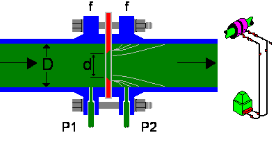
Orifice plate The flow measurement using an orifice plate is based on the application of energy conservation to a flow, measuring the difference in pressure between two points (P1 and P2), at these points the flow has different speeds. This speed change is caused by a reduction in area. The orifice plate installed in the pipeline causes an increase in flow velocity and a corresponding decrease in pressure (see Figure 1 below).
The equation that governs the use of these devices will be Bernoulli's equation in case of incompressible flows (liquids) or the first law of thermodynamics for the compressible flows (gases). It should be noted however that the energy equation can be written in a very similar way to the Bernoulli equation under certain flow conditions, therefore the equation used in common practice comes from the Bernoulli equation and the factor correction of the fluid compressibility Orifice plates are still the most widely used type of flowmeter in the world today. To calculate the flow rate must be all data available below (section Gas):
The difference between Gas and liquid flow rate is:
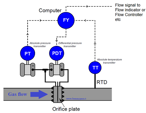
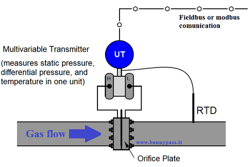
The Rosemount model 3095MV and Yokogawa model EJX910 are examples of multi-variable transmitters designed to perform compensated gas flow measurement, equipped with multiple pressure sensors, a connection port for an RTD temperature sensor, and sufficient digital computing power to continuously calculate the flow rate based on the AGA equation (see Figure 3 below)
While in terms of cost and installation, this type of transmitter is more comfortable but in some petrochemical plants still is forbidden, especially in the safety system. Even if Fieldbus in the last years has become very stable, according to some technical acknowledge (managers), it is still not reliable. The calculations for determining the flow rate from the pressure drop are derived from fairly straightforward physical equations. There are a number of variables, however, each with its own engineering units. These include orifice geometry, pipe dimensions, fluid viscosity and fluid density. Due to the number of terms and the conversion factors involved for each variable, the calculations can get quite involved. Fortunately, there are a lot of online calculators like in this article here below that let you simply enter the variables in whatever engineering (units which are better for you), and then calculate the flow rate for any pressure drop across the orifice. Automatic flow rate calculator in m3/h
Available also Daniel Orifice Calculation here. For more details read the article Controller square root or linear flow rate For more details see the PDFs below
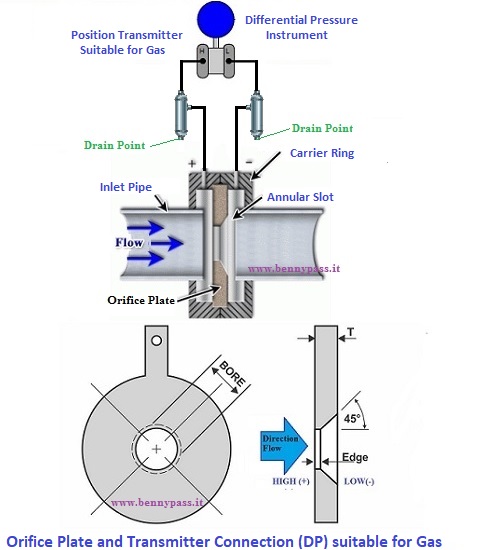
The photo below is a typical connection for gas production
Conclusion and Recommendations
|


+(39) 347 051 5328
Italy - Kazakhstan


09.00am to 18.00pm
About
We offer the best and economical solutions, backed by 27+ years of experience and international standards knowledge, echnological changes, and industrial systems.
Our Services
Marketing Materials


Marketing Materials1


