
|
The Hydraulic Solenoid Valve and Spool valve
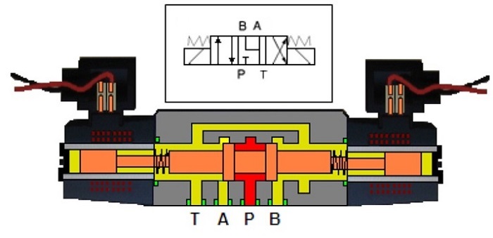
These are the control valves most used in hydraulic circuits and work with an electric control that can be given by a limit switch, by a pressure switch/transducer or by a manual electric button and are called direct drive because the spool is moved directly from the strength of a coil. The material of the body valve is in metal (cast iron, steel, aluminium) and includes hydraulic connections or plate mounting. The spool/slider/drawer is a small steel cylinder machined with tight tolerances to obtain metal-to-metal seals.
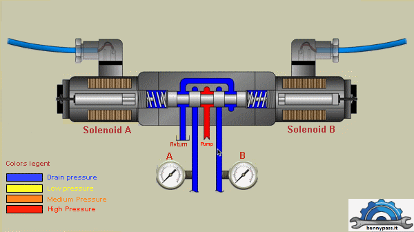
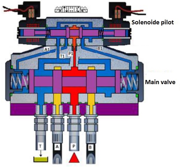
As you can see from the photo above there are 4 points all described below:
The hydraulic oil supply P (from the Pump) supplies oil to A or B depending on which solenoid is energized. Based on the circuit, the solenoid can supply one output at a time, A or B never both otherwise the internal shaft will not move. Normally, this type of solenoid is installed on hydraulic circuits where interlocking protection is required, like lifting the arm of a Crane with hydraulic oil, etc.
Let's see exactly how the circuit works through the drawing
Figure below shows the solenoid animation
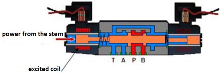
Internal Coil The operation of the valve is given by the electromagnetic force that develops the solenoids, which by moving the spool to the desired position, open the lights involved for the correct sequence of the hydraulic circuit. The solenoid is the element that transforms the magnetic energy by a coil into an electromagnetic force which able to move the spool of the valve and overcome the contrast of the spring.
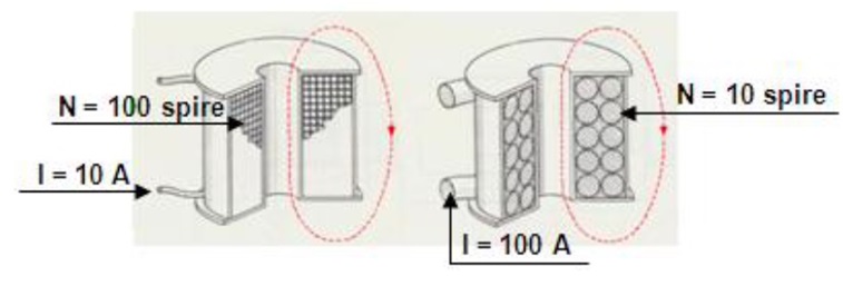
To understand how it works, we need to know that every current-carrying conductor is surrounded by a magnetic field (practically a magnet). If the conductor has the shape of a coil, as in the drawing above, the magnetic field is strengthened according to the ratio of the number of turns of the coil itself. The drawing above shows two different construction coils, below differences:
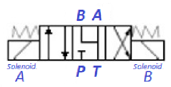
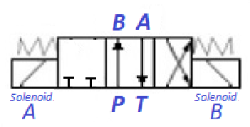
Both generate equal magnetic fields. For the magnetic field, the intensity of current and the number of turns N are decisive, their product is called magnetomotive force, whose symbol is θ (Theta). The relation that defines the driving force is: θ = ???? ∙ ????. The exchange of position in a solenoid valve takes place when a solenoid is excited by an electric current that generates a magnetic field, attracting the spool which is in metal. In the figure below an electric signal is sent to the left coil, the solenoid generates a magnetic field and draws the shaft to the right and consequently passes from the rest position to the P connection with B and remains in the same condition until the solenoid will be de-energized.
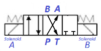
If removing the voltage from coil, the loaded spring pushes the drawer into the central resting position. To reverse the flow direction it is necessary to excite the right coil which pushes the spool to the left and then connects the light P with A. The supply voltage of the coils can be in direct current DC (DC) 12 or 24 volts or alternating current AC (AC) 110 or 220 volts-50 Hz. The magnets are realized in two versions: dry or in oil bath and must comply with insulation classes according to the operating temperature in accordingcontacts, including the tightness to the penetration of liquids and external material. The degree of protection is highlighted with the initials IP (International Protection) followed: by a double-digit number, for example: IP 65. The first digit "6" is related to the protection of the contacts under live voltage, internal parts in movement, or the penetration of external material like dust. The second digit "5" establishes protection from the penetration of liquids like water jets.
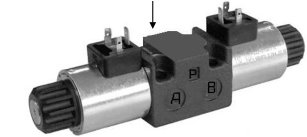
The figure above shows the plate with identification code which shows the code of the valve and the size, the type of spool/slider, the gaskets, the supply voltage (D.C or A.C), the electrical connection of the coil
The characteristic that defines the dimension of a valve is called "size" which is a function of the maximum pressure/flow that it can guarantee, all certificated by ISO 5738 which is the standard regulation. The most used in hydraulics systems (range) they start from size 3 to 10 and comply with CETOP standards. For an exact choice, it is always advisable to check the technical datasheet on the manufacturers' catalogues, which indicate diagrams, load losses, electrical part type, etc. The valve described is directly controlled and can work with a maximum flow of 130 l / min. at a pressure of 320 bars. When these parameters are exceeded, the indirect or double-stage solenoid valves must be used.
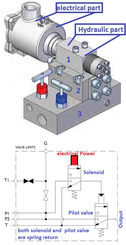
The central position is obtained by removing current from the pilot valves (solenoids) in such a way that the pilot and main distributor slides are moved to a central position through the springs calibrated to the same force. All the valves are connected to the circuit with two typology types of connections: Threaded or plate. The figure above shows as the fittings hose connection is screwed to a base plate (violet) on which the valve is installed. The valve is held in place by suitable fixing screws and with interposed relative gaskets. The construction of the plate or sub-base must comply with the ISO 4401 standard which guarantees interchangeability standards between the various manufacturers. In the one block assembly is required that all the valves are grouped into a single housing. In this way, the possibility of leakage will be very remote.
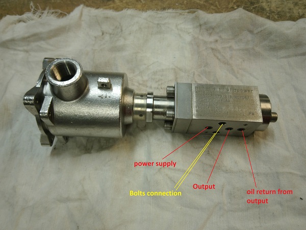
The solenoid above (manufacturer Bifold) is one of the most used solenoids in Oil&Gas. According to our experience, this solenoid is one of the best on the market (very reliable). Unfortunately, when the hydraulic systems are dirty, the first things that will be damaged are the solenoids. As you can see in the photo, the solenoid is divided into two parts, 1 and 2, in addition there is also the base connection (3) below the details:
There are also other types of solenoids like as the article here
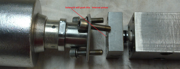
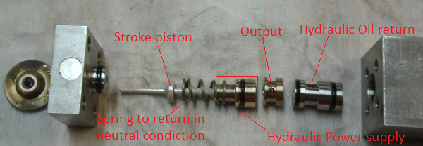
The Figure below shows a Solenoid which is open for internal inspection
The Figure below shows the internal parts
As you can see it is built very well, but like all other solenoids under high hydraulic pressures it suffers a lot from dirt and also if remains for a long time in the same position. In most cases, the pieces that are damaged are stroke pistons and O-rings.
Conclusion The solenoid shown in Figure above is a solenoid from the BIFOLD (model FP8003). There are many models but all the same in terms of working principle. Without any doubt, they are highly safe and reliable solenoids This type of solenoid requires a minimum hydraulic pressure to energize the internal part, for more information see the datasheet here or more details here There is also the internal repair kit instead of changing the entire solenoid, contact BIFOLD or send a message here, our specialist will try to help you.
|


+(39) 347 051 5328
Italy - Kazakhstan


09.00am to 18.00pm
About
We offer the best and economical solutions, backed by 27+ years of experience and international standards knowledge, echnological changes, and industrial systems.
Our Services
Marketing Materials


Marketing Materials1


