Stabilized power supply from 230 Volts to 9-20 Volts with 2N3055
A power supply specifically designed to power transceivers or to test electronic ignitions. In fact, according to the characteristic table, this power supply is capable of providing perfectly stabilized voltages from 9 to 20 volts, at 8 amps and above.
Whoever owns a CB transceiver or a medium power 144 MHz transceiver, when will decide to use his device feeding it directly from the network (220 volts), may find himself in difficulty. In fact, the various power supplies that can be found on the market only rarely manage to deliver a current greater than 1.8 amperes, while those who can reach 3 / 3.5 amperes have prices so high as to discourage any eventual purchase.
Knowing these difficulties, we wanted to create a stabilized power supply suitable for use in AF; since this power supply can deliver high currents of around 8 amps (which we can increase to 10-12 amps by inserting, as we will explain, an extra transistor on the final stage), we can also use it to test electronic ignitions or other robust equipment, of course, the power supply voltage must be between 9 and 20 Volts. The main features of this power supply are as follows:
- Adjustable voltage from 9 to 20 volts
- The maximum current between 7 and 8 amps
- Short circuit protection
- The current limit is adjustable from 0.5 to 7.5 amps
- Residual AC with a load of 7.5 amps = 40 millivolts pp
- Voltage variation at 12 volts with a load of 7.5 amps = 50 -70 millivolts
- Voltage change at 12 volts with 3 amps load = 10 ~ 15 millivolts
- Stabilization time by inserting or removing a strong load = 1 sec.
- Stabilization circuit protected against any AF residues
- Transistors used = n. 5
Characteristics of the power supply
- The power transformer T1 is the most important component of the whole circuit; he must be the first able to deliver the required current on its secondary circuit. It is easy to understand that, if the secondary winding is capable of delivering a maximum current of 5 amperes only, we will obtain a stabilized voltage at the output (as desired), but with a current of 5 amperes only; but if the secondary can deliver 8 amperes, this will be the maximum current that we can draw from it. The maximum power of the lamellar pack for this transformer must be between 180-200 watts. The alternating voltage that can be supplied must be between 23-25 times alternating.
- The four rectifying diodes for the bridge must be chosen suitable for the currents require; that is, it is necessary to choose silicon diodes of 5O / 8O volts and 10-15 amperes. Otherwise, a well-sized transformer would be useless if the diodes would not allow the passage of the required current. The correct diodes which I prefer are the diodes 21PT20 (see datasheet)
- The voltage, rectified by the diode bridge, and smoothed by the two high capacity electrolytic capacitors (indicated in the wiring diagram with the initials C1 and C2), then applied as the transistors power supply
- The transistor TR1, a silicon PNP, is used in this circuit exclusively as a current stabilizer to make the transistor TR2 absorb a constant current, even when the collector voltage varies (see datasheet). In fact, by rotating the trimmer R5, i.e., polarizing the base of TR2 more or less on the collector, it will be a voltage variation, which is later useful to polarize the base of the pilot transistor TR3. Being supplied with constant current, TR2, in fact, produces strong variations in the collector voltage, even for small variations in the output voltage applied to the base, which is controlled by dividers R4, R5, R6, thus increasing stabilization. From the emitter of TR3, we will take the current necessary to drive the bases of the two final transistors placed in parallel, and from the two emitters of these, we will take the stabilized tensions as output.
- The two resistors R8 and R9 placed in series in the two emitters of TR4 and TR5, are indispensable to compensate for any beta differences of the two final transistors. In this regard, we can anticipate to the reader that instead of two 2N3055 finals, it is also possible to connect three or four (2N3055), thus obtaining a current of 12-15 amper at the output (transformer permitting). When adding in parallel to the existing ones of the other 2N3055s as finals, it is always necessary to remember to apply, on the emitter of each of them, a 0.5-ohm 10-watt wire resistor (see RB - R9)
Wiring Diagram
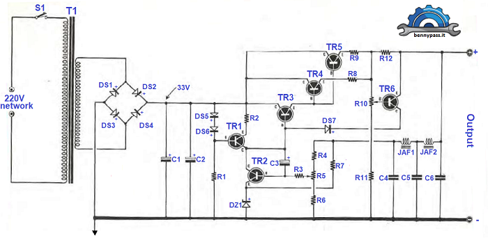
Figure 2 wiring diagram
| Component list |
- R1= 2.2kΩ 1/2 watt
- R2= 68Ω 1/2 watt
- R3= 10Ω 1/2 watt
- R4= 1.2KΩ 1/2 watt
- R5= 1KΩ Trimmer
- R6= 1KΩ 1/2 watt
- R7= 1KΩ 1/2 watt
- R8= 0.45/0.5Ω 7-10 watt (flush)
- R9= 0.45/0.5Ω 7-10 watt (flush)
- R10= 470Ω Trimmer
- R11= 2.2kΩ 1/2 watt
- R12= 0.22/0.25Ω 7-10 watt (flush)
- C1= 2000µF 50-60V (electrolytic)
- C2= 2000µF 50-60V (electrolytic)
- C3= 47-50µF 25V (electrolytic)
- C4= 33000pF 25V (polyester)
|
- C5= 10000pF 25V (polyester)
- C6= 33000pF 25V (polyester)
- DS1 a DS4= 1N4007
- DZ1= diode zener 5.6V 1/2 watt
- JAF1-JAF2= AF impedance VK200
- TR1= Transistor PNP BD140
- TR2= Transistor NPN BD139
- TR3= Transistor NPN 2N3055
- TR4 - TR5= Transistor NPN 2N3055
- TR6= Transistor NPN BC107 or BC208B
- S1= Mains switch
- T1= The transformer of 200 watts (more or less) with secondary of 23-25Volts 8 amps
|
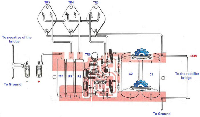
Figure 2 shows the printed circuit
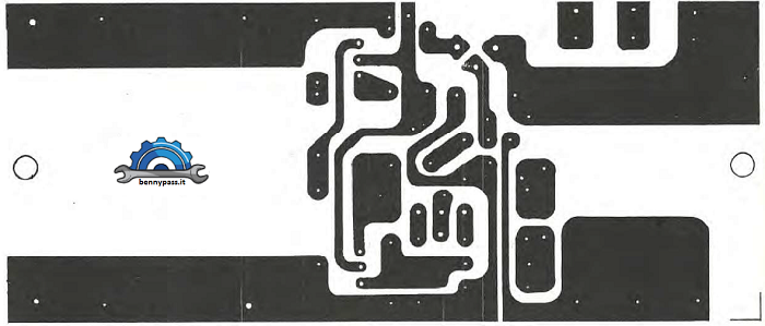
Figure 2 printed circuit
The Power Diode
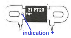
Figure 4 The Power Diode
Figure 4 show the power diodes used for the rectifier bridge are represented in the drawing (figure 4). To distinguish the positive terminal from the negative, the reader must check which of the two terminals is indicate a small circle; that terminal is positive.
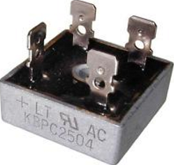
Instead of using single diodes, you can also use the rectifier bridge with all 4 diodes built into it, as long as its amperage is respected. The bridge in the figure below is the one that fits.
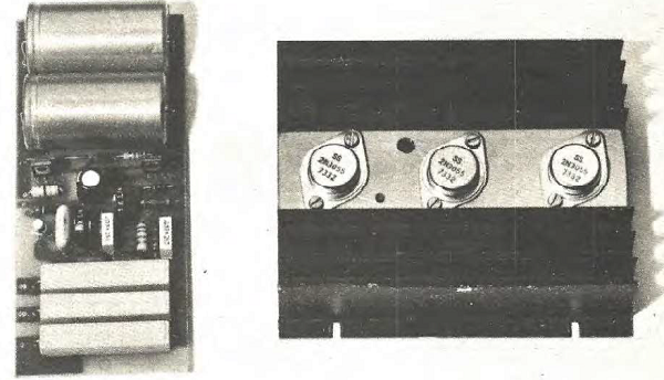
The connection between transformer and diode
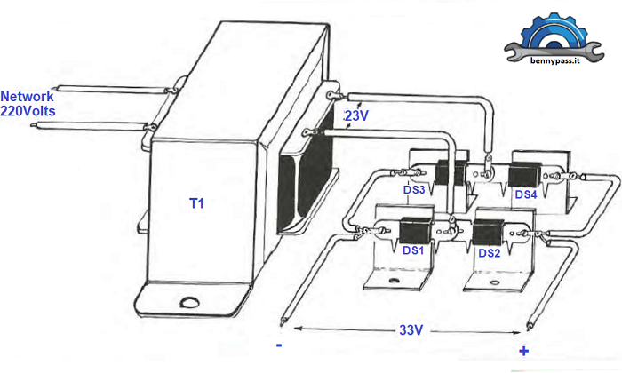
Figure 5 diode connection
As you can see from figure 5, the diodes have been fixed on the special cooling fins. This is very important for the long life of the diodes.
The connection between all other components
Conclusion
This power supply has nothing to envy with other more modern stabilized power supplies. I personally built this power supply 20 years ago, and it still works without any problems. The 2N3055 final transistors I know very well, and they are really mules.
Unfortunately, the 2n3055 transistors are very old, and it is not easy to find them in the shop, except if you can't find a shop that has some stocks.
If somebody wants to build this power supply is available in our store the 2N3055 and also the circuit board.
www.bennypass.it
|


