
|
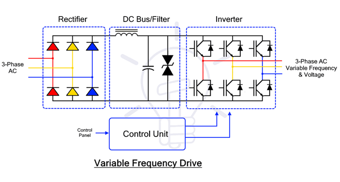
VFD (Variable Frequency Drive) A VFD Motor Manager controls electric motor speed by converting fixed AC power to adjustable frequency/voltage, using three stages: Rectification (AC to DC), a DC Bus (smoothing/storing), and Inversion (DC to variable frequency/voltage AC via IGBTs and Pulse Width Modulation (PWM), allowing precise speed/torque control, smoother starts, and energy savings by matching power to load requirements.
Here's a breakdown of the working principle
Key Benefits
A Variable Frequency Drive (VFD), also commonly known as a motor manager or motor controller, works by converting fixed-frequency utility power into variable-frequency and variable-voltage output to precisely control an AC motor's speed and torque. Core Working Principle: The Three-Stage Journey The VFD operates through three primary power conversion stages managed by a central microprocessor.
Key Control Parameters To manage the motor effectively, the VFD maintains specific relationships between electrical signals:
Integrated Management Features Modern VFD "Motor Managers" do more than just change speed; they provide comprehensive system protection and optimization:
How it works in three Step AC - DC- AC
Key benefits
Also known as
Common applications
|
|
Type of earthing System earthing There are three main earthing drawing for electrical systems (TT, TN, IT), based on the connection between neutral and earth, and various physical types of earth electrodes such as rods, ropes, plates, chosen based on safety requirements and the characteristics of the terrain, with the aim of ensuring the safety of people and the correct functioning of the systems.
Earthing schemes (according to IEC 60364)
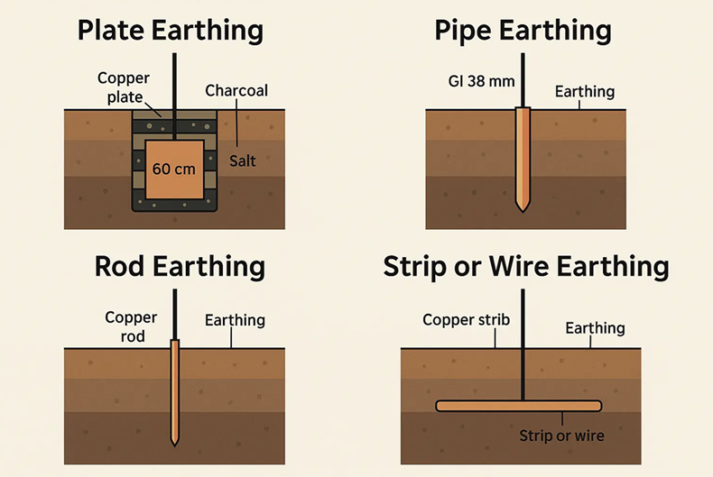
Common Types of Earth Electrodes & Connections
How the Connection is Made (General Principles)
Physical earth electrodes are categorized by their shape and installation method to establish a low-resistance connection with the ground.
Common Physical Types
Connection Methods To ensure durability and electrical continuity, connections to these electrodes are made through several standard methods:
|
Super User
Electrical
|
MCC PANEL WORKING PRINCIPLE An MCC (Motor Control Center) panel works as a central command center for managing multiple motors, distributing power through main breakers to individual motor starters (like DOL, Star-Delta, or VFDs) housed in modular "buckets," and providing protection via circuit breakers, fuses, and overload relays, enabling centralized start/stop control, monitoring, and automation integration (PLC/SCADA) for industrial processes. For more details see the video below
You can also see a practical demonstration of the components in this video: Key Functions
The working principle of a Motor Control Center (MCC) panel centers on consolidating the power distribution and protection of multiple electric motors into a single, modular enclosure. It acts as a "command center," receiving incoming power and distributing it through a common busbar system to individual control units known as "buckets" or "feeders". Core Working Process
Key Components
Advanced "Intelligent" MCCs (iMCC) In 2026, many industrial facilities use Intelligent MCCs that integrate microprocessors and communication protocols (like Profibus or Ethernet). These panels allow for predictive maintenance by tracking motor health data and enabling precise remote adjustments without manual intervention. |
Super User
Electrical
|
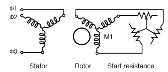
Wound Rotor Induction Motors A wound rotor induction motor has a stator like a squirrel cage induction motor, but a rotor with insulated windings brought out via slip rings and brushes.
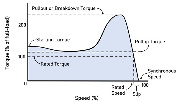
Figure 1 -Wound rotor induction motor Q: Why put resistance in series with the rotor?
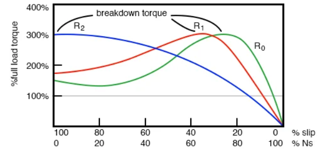
Figure 2 -Breakdown torque Breakdown torque peak is shifted to zero speed by increasing rotor resistance The resistance decreases the torque available at full running speed. But that resistance is shorted out by the time the rotor is started. A shorted rotor operates like a squirrel cage rotor. The heat generated during starting is mostly dissipated external to the motor in the starting resistance. Speed Control Motor speed may be varied by putting variable resistance back into the rotor circuit. This reduces the rotor current and speed. The high starting torque available at zero speed, the downshifted break down torque, is not available at high speed.
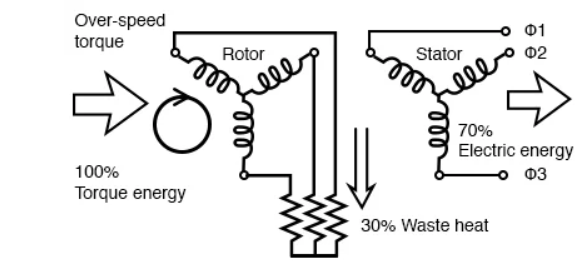
Figure 3 - Speed curve for induction Motors Doubly-fed Induction Generator We previously described a squirrel cage induction motor acting as a generator if driven faster than the synchronous speed. (See Induction motor alternator) This is a singly-fed induction generator, having electrical connections only to the stator windings.
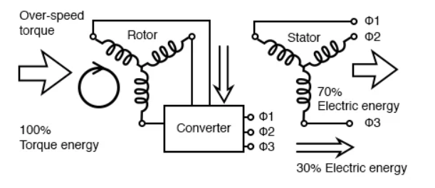
Figure 4- Rotor resistance allows over-speed of doubly-fed induction generator The singly-fed induction generator only had a usable slip range of 1% when driven by troublesome wind torque. Since the speed of a wound rotor induction motor may be controlled over a range of 50-100% by inserting resistance in the rotor, we may expect the same of the doubly-fed induction generator.
Figure 5 - Converter recovers energy from the rotor of the doubly-fed induction generator In actual practice, the rotor resistance may be replaced by a converter absorbing power from the rotor, and feeding power into the power line instead of dissipating it. This improves the efficiency of the generator.
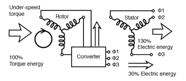
Figure 6 - Converter borrows energy from the power line for the rotor of the doubly-fed induction generator, allowing it to function well under the synchronous speed The converter may “borrow” power from the line for the under-speed rotor, which passes it on to the stator. The borrowed power, along with the larger shaft energy, passes to the stator which is connected to the power line. Wound Rotor Induction Motor Qualities
|
|
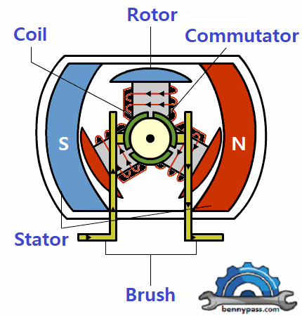
Brushless DC Motors A motor converts supplied electrical energy into mechanical energy. Various types of motors are in common use. Among these, brushless DC motors (BLDC) feature high efficiency and excellent controllability, and are widely used in many applications. The BLDC motor has power-saving advantages relative to other motor types. Motors are Power Delivery Machines When engineers are faced with the challenge of designing electrical equipment to perform mechanical tasks, they might think about how electrical signals get converted to energy. So actuators and motors are among the devices that convert electrical signals into motion. Motors exchange electrical energy to mechanical energy. The simplest type of motor is the brushed DC motor. In this type of motor, electrical current is passed through coils that are arranged within a fixed magnetic field. The current generates magnetic fields in the coils; this causes the coil assembly to rotate, as each coil is pushed away from the like pole and pulled toward the unlike pole of the fixed field. To maintain rotation, it is necessary to continually reverse the current—so that coil polarities will continually flip, causing the coils to continue “chasing” the unlike fixed poles. Power to the coils is supplied through fixed conductive brushes that make contact with a rotating commutator; it is the rotation of the commutator that causes the reversal of the current through the coils. The commutator and brushes are the key components distinguishing the brushed DC motor from other motor types. Figure 1 illustrates the general principle of the brushed motor.
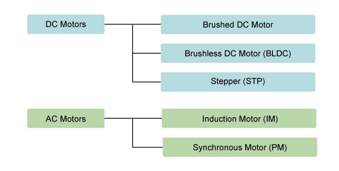
Figure 1 - General principle of the brushed motor Fixed brushes supply electric energy to the rotating commutator. As the commutator rotates, it continually flips the direction of the current into the coils, reversing the coil polarities so that the coils maintain rightward rotation. The commutator rotates because it is attached to the rotor on which the coils are mounted. Common Motor Types Motors differ according to their power type (AC or DC) and their method for generating rotation (Figure 2). Below, we look briefly at the features and uses of each type.
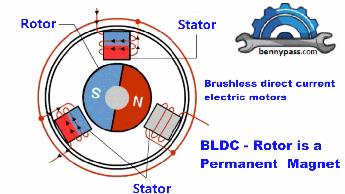
Figure 2 - Different Motors Brushed DC motors, featuring simple design and easy control, are widely used to open and close disk trays. In cars, they are often used for retracting, extending, and positioning electrically powered side windows. The low cost of these motors makes them suitable for many uses. One drawback, however, is that brushes and commutators tend to wear relatively quickly as a result of their continued contact, requiring frequent replacement and periodic maintenance. There are various types of motors in common use. In this session, we look at the advantages and applications of brushless DC motors. Why Do BLDC Motors Turn? As their name implies, brushless DC motors do not use brushes. With brushed motors, the brushes deliver current through the commutator into the coils on the rotor. So how does a brushless motor pass current to the rotor coils? It doesn’t—because the coils are not located on the rotor. Instead, the rotor is a permanent magnet; the coils do not rotate, but are instead fixed in place on the stator. Because the coils do not move, there is no need for brushes and a commutator. (See Figure. 3.) Figure 3 - A BLDC Motor (Brushless direct current electric motors) Since the rotor is a permanent magnet, it needs no current, eliminating the need for brushes and a commutator. The current to the fixed coils is controlled from the outside. Advantages of BLDC Motors A BLDC motor with three coils on the stator will have six electrical wires (two to each coil) extending from these coils. In most implementations, three of these wires will be connected internally, with the three remaining wires extending from the motor body (in contrast to the two wires extending from the brushed motor described earlier). Wiring in the BLDC motor case is more complicated than simply connecting the power cell’s positive and negative terminals; we will look more closely at how these motors work in the second session of this series. Below, we conclude by looking at the advantages of BLDC motors. Ideal Applications for BLDC Motors We’ve seen that BLDC motors offer high efficiency and controllability and that they have a long operating life. So what are they good for? Because of their efficiency and longevity, they are widely used in devices that run continuously. They have long been used in washing machines, air conditioners, and other consumer electronics; and more recently, they appear in fans, where their high efficiency has contributed to a significant reduction in power consumption. Toward Wider Usage in the Future We can expect to see BLDC motors used in a wider range of applications in the future. For example, they will probably be widely used to drive service robots—small robots that deliver services in fields other than manufacturing. One might think that stepper motors would be more suitable in this type of application, where pulses could be used to precisely control positioning. But BLDC motors are better suited to controlling the force. And with a stepper motor, holding the position of a structure such as a robot arm would require a relatively large and continuous current. With a BLDC motor, all that would be required is a current proportionate to the external force—allowing for more power-efficient control. BLDC motors may also be replacing simple brushed DC motors in golf carts and mobility carts. In addition to their better efficiency, BLDC motors can also deliver more precise control—which in turn can further extend battery life. |

+(39) 347 051 5328
Italy - Kazakhstan


09.00am to 18.00pm
About
We offer the best and economical solutions, backed by 27+ years of experience and international standards knowledge, echnological changes, and industrial systems.
Our Services
Marketing Materials


Marketing Materials1


